current limiting resistance 9401
I have a couple of 9401 modules DIO for my cDAQmx and I want to use some of these lines as inputs to detect (and trigger) relay contacts. On page 9 of the manual 9401, it shows how to convert essentially a + external 5 V signals and a set of contacts of the switch to an input signal correct 'TTL' (see the 'Dev 2"in attachment). My question is: what is a good value for this current limiting resistor? I will plunge at least 4 channels of a current value in each module. My first thought is to maintain the relatively low current (1-2 my), but since I send you these currents in a noisy environment of the electromechanical relays should I boost the current level up to avoid wrong signal?
Hey
It depends on what current you want to drive, I found this document which could help you determine also check what DF.
Good luck
Lab
Tags: NI Hardware
Similar Questions
-
Hello
After reading everything that specifications and manuals, I decided to ask a general question.
In the data sheets, user guides I've read, in general, there are two warnings for DIO:
-Do not connect the outputs digital circuits which operates above the limits.
-Do not drive the line with tensions outside its operating range.
Generally speaking they tell me I need to know when dealing with output and voltage when dealing with entries. So I have this question, can I wire a power supply for digital inputs directly without exceeding its "beach of normal operation and without any protection circuit? In fact, my feelings, this is not possible. But why certain documents produced clearly mention that the impedance internal inputs while that of others is not clear those? How can I determine if I can connect a signal directly to an entry (for example USB-6525 indicates a current limiter circuit, but I don't see a clear explanation in the datasheet USB-6251)?
As long as the input voltages are within specified limits, no damage will be the DAQ hardware. Logic devices often have two lines of non overlapping input, one for low input and high input. If the input voltage lies between the beaches, the performance of the device can be unpredictable. Also, check your power supply to make sure that this doesn't not exceeding when turned on or off as that could exceed the DAQ limit.
Lynn
-
AutoScale is independently performed the current limits of the view.
Hello
I work with a ScatterGraph with the number of plots in it.
When I put the YAxis AutoScale Mode, auto-scaling is performed independently of the graphics currently displayed.
For example:
If my graphics maximum peak value is 100 and the minimum value is 0, but the displayed range values range between 4 and 10, the graph will always evolve to 0-100.
p.s. is there anything like the function AutoScaleNow() for c#?
I use the "Measurement Studio 8.1.2.472"
Thanks for help
Danny,
Measurement Studio does not provide a function to do what you are looking for. The solution that you cooked up with to examine all items displayed and find the Max and Min Y and then manually by setting the YAxis brought to these values chart is probably the best solution. I'll drop a suggestion for this feature to add to Measurement Studio product.
Kind regards
ADri Kruger
-
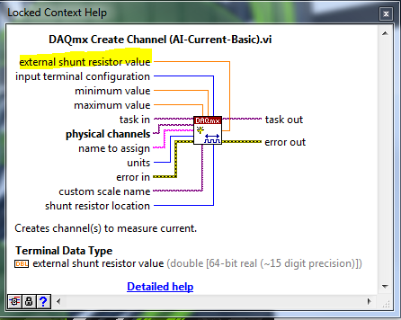
DAQmx shunt for current acquisition resistance setting
Hello
I'm using LabVIEW with a DAQmx (6353 USB) and I want to do a power outlet. For this, I have a shunt resistance. But I would like to pass the value of the parameter of the task of acquiring resistance. Do you know if it's possible?
Thank you
Do not use the DAQ assistant. You can use it to configure your task but then right-click on it and convert it to the DAQmx code.
The DAQmx create channel VI has an entry for the external shunt resistance value.
-
Video capabilities - confirming the current Limitations (check + superior quality Sorenson)
Hello
Video with Cocomo, I wrote confirm that the current version does not provide the features of two following regarding:
- Record. Acrobat Connect Pro includes record capability. I believe, that now Cocomo has not (yet) include the ability to check?
- Video encoding. Am I right that at this time Cocomo supports only Sorenson Spark for acquisition of online video? (Background: I have two clients who seek integrated graphics subsystem and chat applications text with a high quality for the main presenter video.) Flash Player supports playback of video encoded in H.264, On2 VP6, and Sorenson Spark. For encoding live video, Flash Player (and by extension Cocomo) encodes only Sorenson Spark. However, also is Adobe, supported via the Flash Media Live Encoder (GFFE) direct using VP6 and H.264 encoding. I guess that Cocomo currently does not support integration with GFFE or any other option for higher quality live video acquisition)
Thanks again for your support and this great new product or service.
I look forward to Cocomo having its official commercial release here in 2009! :-)
Best regards
gHi Greg,.
You're right - recording is not (yet) supported =). Could you give us more details about what you think of using a recording for?
For encoding, you're right again, Cocomo did only what the Player did - we have plenty of all real time encoding farms (which, if you're always capture via the Flash Player, then re-encoding to H264 on the server is not actually buy you new quality). Personally, I think the right place to apply some pressure is with people from player, to get some updated more modern encoders in the drive itself (believe me, I'm on it, but more votes always help =).
Thank you - hearing more than your use case is always really valuable for us as well!
Nigel -
I have a question for the SMU 4139.
It is able to program the output resistance/impedance.
Its output can be used to simulate a resistance? Floating? Or he is still stuck to the ground.
THX.
Hi kdCMC,
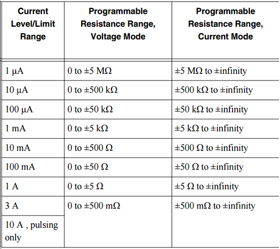
You can program the 4139 NOR as a programmable load. The attached example allows you to use the functionality of the programmable output to the program directly resistance the resistance of the device. To do this using the DCV, set the output voltage to 0 V and the resistance value of the output to a value valid for the given current limit range. DCI mode, set the current 0a output and the output resistance to a valid value for the given value of current level range.
Valid values of resistance are shown below (copied from the technical document):
Note that valid resistance values depends on if you are in mode voltage or DC current. The value of values also depened on the current limiting current level range or that you have programmed.
The load will always float unless you physically short the LO Terminal to the chassis GND.
-
9234 sensor back to resistance of the chassis
My question is about the NI 9234 module and terminal return (HAVE) resistance to the chassis. On the side of the module, the diagram shows a 50 Ohm resistor to the chassis. However, when measured using a multimeter, the resistance is much higher (order 500 kohm.) I hope someone might be able to explain this discrepancy. My only thought is that, based on the data sheet, there are current limiting diodes present between performance and 50 Ohm resistance that may have an impact on the measurement. I don't understand how it would be possible, however. Any help is appreciated.
Page 11 of the Manual:
http://www.NI.com/PDF/manuals/374238c.PDF
Watch back to back diodes in series with the 50 ohm. They are probably affecting your measure if your DMM does not exceed the voltage of conduction of them (don't know what the specs are on the diodes).
-AK2DM
-
You are currently covered by purchase
Like solving where this account that I got from asking for help so that your account can return to normal, I thank
This picture of the place where the problem on my account

a message that is given, it was that you are currently limited services purchasing or redeeming vouchers. Please contact Customer Support to review the status of your account.
SAYA MAH APAPlease help me sorry my English so bad, I'm from Indonesia
Help me at all
SAYA MAH APA -
I can measure the speed of the NI 9401 fan & cRIO 9075 under Scan Interface?
Hello
I am currently using OR 9401 & cRIO 9075 to develop a project, which is to control the CPU fans.
Since I have to communicate with other instruments by serial port, while I have a NI 9870 module to implement the instrument control.
I finished the part of control instrument under scan mode and would like to add the function of the fan speed reading.
Now, I wonder if there is a problem when I choose the Scan Interface to deverlop the program.
I found the following tutorial, he uses the FPGA interface to impement the acquisition of control and PWM frequency.
http://www.NI.com/white-paper/3230/en/
So if the function of the fan control only developed under an FPGA interface, I have to rewrite the control instrument part, seems to be a bit complicated...
You can use the hybrid mode.
http://digital.NI.com/public.nsf/allkb/0DB7FEF37C26AF85862575C400531690
-
I use the SMU 4140 to measure the curves of voltage/current for the transistors - it sets a voltage & I read (not necessarily on the same channel). But I noticed a peculiarity in the data according to the current limit.
First of all, I get different results if I let him autorange device compared to manually set the current limit.
In particular, there is a current lag that occurs for differnent current limits.
In the attached file, the current is allowed to Auto for the Red data and fixed at 100 Ma for data in blue. [the axes are current drain source - ID- & door - Source voltage VGS]
Any idea what is the origin of the offset .02mA in the Red data?
Thank you for following up with an explanation.
Looks like this resource to answer your question:
http://digital.NI.com/public.nsf/allkb/EE869FC813944EAC862578F0005519F5
-
R series: compared to current output output impedance adaptation
Hello
I wonder about the output impedance specified for SMU-782xR and some other adapter module ike l 6581.
The specified output impedance is 50 ohms. To get the best signal integrity, it is imperative to adapt the impedance using a cable (transmission line) with a 0 hm 50 characteristic impedance and impedance of 50 ohm load.
But I don't understand how this is possible, because with a high level of 3.3 v, the output current proposed spindle must be 66 my. The current per output pin max 7821R is 4 my.
This FPGA offer 128 pins, so that the maximum total output current should be of 8.5 A, so 28 w. It's not realistic!
Could someone explain why outputs are 50 ohms?
And how do I adjust the line and the termination of employment?
Thank you and best regards,
Benoit Chantepie
Benedict,
After some thought, the concept of the output impedance is really not applicable outputs logical digital because they spend most of their time in the saturated States and time spent in the transitory States is not usually specified with the exception of the time limits.
What is your purchasing process is I would ignore the specification of output impedance. Watch the voltage and current limits. If those who do not meet your needs, consider external buffers. You can specify the buffer to meet the requirements of your testbed (including protection against defects if necessary) and to meet the specifications of the devices OR.
Lynn
-
Limitations of data Dashboard App
I have an application that requires a central logging Windows PC/Labview make data available for viewing on the screens of multiple users.
Screen touchscreen devices offer the best solution for the environment and I assess tablets under the dashboard of data app vs Windows touchscreen tablet PC running labview code.
The requirement is very flexible because users must each be able to see a selection of a large number of variables against each other or time and also to choose the period of time for display.
I can see the application of the dashboard of data is in constant development and I tested it with data from the trial, including several line plots and be able to zoom and scroll the screens as well as control static variable to select the data to be represented graphically.
However I come to the conclusion that I need to go the Tablet full PC channel to use the full power of Labview to make a user interface appropriate.
I would like to just following current limitations of the dashboard data confirmation:
(i) I can only have one axis Y multiplot graphs/Charts. (and cannot specify the different colors of the locations)
(II) it is not possible to simply provide a timestamp on the X axis.
(III) such things as 3D curves are currently impossible!
(IV) I get about 20000 points for each of the variables at least 10 and this seems to slow down the 1.5 GHz/1 GB of RAM Dual Core tablet that I currently use. Power/memory of treatment more that would help?
Thanks a lot for reading.
You will probably get the best response if you post to the Office of dashboard of data.
-
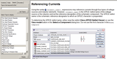
Branch voltage source currents abm
Hello
How to access the current through resistance in the voltage ABM source?
I finally managed to access the current through the resistance. Others may see "Common SEO" in the Multisim help.
-
It is current on the analog module USB NI 9263 output voltage limit (+/-10 v)?
It is current on the analog module USB NI 9263 output voltage limit (+/-10 v)? I try to run a current controlled resistance, but cannot get the required current. The servovalved has a parallel internal resistance of 80 ohms and requires 20 my full operation. Ohm's law: (.02 A) * ((80*80) /(80+80) ohms = 4.5 v) Yet, the required voltage, do not move the servo. Outside the material error (continue this by other means), what could be the problem?
Have you checked the Manual?
Page 12 1 says my.
For servo, you really need some kind of amplifier. See if the manufacturer provides the electronic driver for it.
-
OR USB-6009 can produce the constant current source/sink?
Hi all
I have a card NI USB DAQ to 6009. I need a battery for constant (charge/discharge current<1mA) and="" simultaneously="" monitor="" its="">
I was wondering if I can use USB-6009 of output constant source/sink of charge/discharge current the battery? I've seen a few threads that says 6009 impossible to output constant son of currents, but other says we can use the digital output to provide the current, but it was not only described how.
Thank you.
All the outputs of the USB-6009 case are sources of tension and all have current limits low. There is no way to generate outputs current controlled directly from this device.
What I would do (and have done) is to build circuits of external current source/sink with an op amp or a transistor and allows you to enable or disable a digital output of the USB-6009. If the current must be adjustable, use an op amp circuit that takes an input of the analog output of the USB-6009 voltage to set the current. Use an analog input channel to monitor the battery voltage.
Lynn
Maybe you are looking for
-
Since installing win 10 win 7 duplex printing does not work on my J6480 all in one. I have the last available at HP installed software HP, but still no luck. I checked all the usual suspect as a control to ensure that the function has been enabed and
-
My wireless mouse freezes and it is not the battery. The only way to make it work is to disconnect the usb for wireless mouse device and plug it in again. Is there something I can do to remedy this? It happened on a different mouse I've had for a
-
Sorry if this seems a simple question but I'm limited in my exp. labview I try to get a value of byte hi.lo but can't seem to figure this simple thing. I know that labview has a feature, but I am limited to the functions of the NXT toolkit which supp
-
HP Officejet Pro 8610: HP Officejet Pro 8610 - cartridge problem
My HP Officejet Pro 8610 has a "Problem of cartridge" error on the display screen. I tried all the troubleshooting steps and it will not erase. I replaced the ink with new genuine HP ink which is the expiration date and I contacted HP. They sent me a
-
Windows defender out time with error next 0x800805b4
Why my windows defender time-out with the error next 0x800805b4