Digital frequency measurement
Dear Sir
I'm working on a test bench that will be used for the tests of fatigue for a suspension, chassis etc. Components of the vehicle will be charged by the hydraulic cylinders. These hydraulic cylinders are controlled by an AO and module (NI9263 & NI9401). Feedback is provided by load cells. Charge these cells are connected with module of AI (NI9201). When a cylinder has reached a certain strength (some amplitude scale NI9201) cylinders stops pulling and will make a move to the outside. This signal is 0 when outgoing and 1 when some force is reached. A green led starts to burn (signal is 1) when force is reached. Now, I want to count the number of times that the signal is 1 so that I can do a security system that limits the amount of incoming and outgoing movements cylinders. Can you help me?
Kind regards
Michael Tielemans
Hi Michael,
Attached you will find the example (project).
Kind regards
Bottom
Tags: NI Software
Similar Questions
-
Labview digital frequency measurement speed
I use a USB-6210 device to measure frequencies of 50 to 1000 Hz I need to connect the frequency every 50ms. I do this for a while loop in labview using a measure of frequency of 1 meter in labview and save the express data using VI. Each iteration of the loop takes at least 60 to 100 ms just read the frequency within the loop. How can I increase the speed of measurement in Labview?
PraveenB,
Here is a table of the terminals of the meter and associated PFI lines. It is available in the NI-DAQmx help. (http://digital.ni.com/public.nsf/allkb/CCDFC93878BD8781862570FC00559980?OpenDocument)
Default meter terminals OR DAQmx
Counter/Timer signal By default the PIN code The signal name CTR 0 SRC 1 PFI 0 CTR DOOR 0 2 PFI 1 CTR 0 TO THE 1 PFI 0 CTR OUT 0 6 PFI 4 CTR 0A 1 PFI 0 CTR 0 Z 3 PFI 2 CTR 0 B 2 PFI 1 CTR 1 CBC 4 PFI 3 CTR 1 DOOR 3 PFI 2 CTR 1 TO THE 4 PFI 3 CTR 1 OUT 7 PFI 5 CTR 1A 4 PFI 3 CTR 1 Z 2 PFI 1 CTR 1 B 3 PFI 2 FREQ ON 8 PFI 6
When you choose 1 meter in the channel to create VI it automatically reserves the door which is PFI2. If you use the counter 0 PFI 2 will work well. Even if you use the 1 meter, you can use anything but 2 PFI.
-
static/digital waveform output and low frequency measurement of voltage - SMU-6358
Hello
1. I have an attached VI [digital_voltage_output] who must generate a logical true or false static state in the output of the device/port0/line1 Word to say. When the VI works I click the button several times, but nothing happens to the port0/lines1.
2 such a thing [digital_voltage_waveform_output_square] if I'm trying to generate a digital waveform to pin the same with the waveform generating VI. If I connect a waveform chart to the output of the generator function VI, then the chart will show me the good waveform I want, but still nothing is written to the text file.
3. I have read the manual for the X series cards, but it remains unclear for me a little how to things of the road in LV I have a measure of the frequency measurement VI low frequency that I downloaded. It offers me the ports for the supply frequency - ctr0, 1, 2, etc. As far as I'm concerned the PFI ports are responsible for these types of actions. How can I find out the LV that I want to connect say ctr0 and pfi0? »
I use LV 8.6.
Thank you
Kriváň
Hi Kriváň,
The problem you had with the choice of a specific digital line as a physical channel, is that the control that was previously used in this example was created for a data acquisition task that uses a whole port rather than a specific line. I was able to overcome this problem by removing the control and recreate. The control now gives you the option to choose the specific digital lines e.g. port0/PXI1Slot2/$line0.
I was also able to overcome the error of-200802 you mentioned. I was able to do this in a real constant of wiring at the entrance to auto-start the VI DAQmx writing then remove the DAQmx beginning the subsequent code VI. The modified code is attached.
I hope this helps.
Best regards
Christian Hartshorne
NIUK
-
Frequency measurement of analog input using DAQmx C APIs on SMU-6341 map
Hello
I use Linux DAQmx and attempt to measure the frequency of analog input using the map DAQ SMU-6341.
There is an ANSI-C frequency measurement example:
/ usr/local/natinst/nidaqmx/examples/ansi_c/Analog_In/Measure_Frequency/Cont_Freq-Int_Clk-SCXI1126
However, the call to DAQmxCreateAIFreqVoltageChan results in the following error:
DAQmx error: selected physical channel does not support the type of measure required by the virtual channel you create.
Create a channel to a type of measure that is supported by the physical channel, or select a physical channel that supports the type of measure.
Property: DAQmx_AI_MeasType
Required value: DAQmx_Val_Freq_Voltage
Possible values: DAQmx_Val_Current, DAQmx_Val_Resistance, DAQmx_Val_Strain_Gage, DAQmx_Val_Temp_BuiltInSensor, DAQmx_Val_Temp_RTD, DAQmx_Val_Temp_Thrmstr, DAQmx_Val_Temp_TC, DAQmx_Val_Voltage, DAQmx_Val_Voltage_CustomWithExcitationTask name: _unnamedTask<0>
State code:-200431
DAQmx does support the function of the frequency on the map 6341, or should we use examples of voltage and calculate the frequency manually?
Frequency of HAVE it is a type of channel that has been supported only on the SCXI module name of the example.
You will need to use a voltage input channel and calculate the frequency manually for your device.
-
PXI-6608 fairer frequency measurement
The attached VI measures the frequency of a known Hz 24,575,000 signal. When measured with a meter of frequency of 3 GHz Agilent 53181 A-010, that measure 24,575,999.4 Hzsignal. When the same signal is measured with the PXI-6608 meter, this signal is 24,576,149.3 Hz. The two instruments are calibrated, and the two measurements were performed with a portal of 8 sec.
I use the more precise measurement technique? My PXI-6608 is defective or out of calibration, although it is brand new?
various Info. :
The PXI-6608 is in slot 2 a PXI-1033. I connect to CTR1 via PFI - 35, triggering on the front and I have a door 8 sec for sub-Hz resolution.
2009 LabVIEW, TestStand 4.2, MAX 4.6.1
Thanks in advance,
Sam Broyles
-
Frequency measurement and phase of a square wave using to extract the information of your unique vi
Hi all
I'm trying to measure the frequency and phase of a square wave from a data acquisition card using vi retrieves your unique information. So far, the frequency can be measured precisely, but there are a few problems with the measurement of phase.
I have attached a sample program here. I generate the wave square using Square Wave PtByPt vi. The default sample size is 1000. When I put the frequency = 7.43, phase = 80, the frequency can be measured precisely, but the phase is completely. Is there something wrong with my program?
Thank you very much for your help.
Best regards
A square wave is not a single signal ;-)
If you have a square wave use the edges to make measurements.
-
Error timeout when using hardware DAQ-6024E frequency measurement
-
frequency of measurement of digital random signal
Hi all.
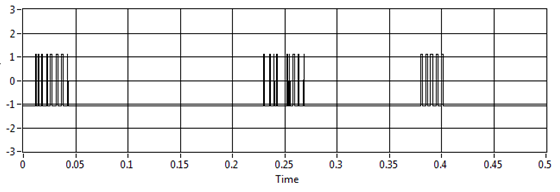
I want to measure the frequency of the signal. This value will be sent to any other device to vibrate the vibrator according to the value.
For example, I want to measure this signal:
I try to use your vi and extract single signal measure vi, but the result is not fair, for example, if I have no pulse on the graph the result is 11, 5 Hz (it should be 0 Hz)
I use assistant NI USB-6210 and acquisition of data to get the data from the sensor
Laughing out loud! All that motivates you... I don't see attachment. I commented on the block diagram on the vi attached which may help. What you can do in your data acquisition program, use is get the queue with the name of data. Then take the waveform of the DAQ assistant and use waveform components get to retrieve the values of the real signal (-1 to 1). Now use a loop with automatic indexing on table of signal and inside use enqueue to place each value of the signal on the data queue. In the joint programme filter, you can either copy the lower node in your program for the acquisition of data, or remove the loop of high signal generation and run them in parallel. The nice thing about the queues is that they can transport data between different vi on the same computer that the name is the same. If you want to do something with the frequency measures, while you can use a different queue for buffering of the data out of the loop of measure.
Good luck!
-
Measurement of high frequency with the NI 9411
Hello
I would like to measure the frequency of a TTL signal with the 9411 OR in a cDAQ-9178 chassis. 1.6 at 48 kHz frequency range.
With examples of Labview digital frequency meter, it is not picking up on the signal. Any advice?
Anna
Hello!
After talking to an applications engineer of NOR, I realized that the input signal must be less than 5 v. In particular, the bass is between 0 - 0.8V and the top is between 2 - 5V.
Once I have limited input to this range, the module of frequency meter picks up on the signal very well.
Thank you
Anna
-
Frequency of measurement with cDAQ NI 9402 chopper
Hello world
I'm new in the world of the cDAQ and try now just get a frequency of a TTL signal output chopper. I confirmed 23 Hz frequency on an oscilloscope. It's a nice clean 5V square wave, but when I try to measure the frequency in labview using a VI (dig frequency of continuous measurement) example, it comes to expire. Trying to look at the entrance of the signal in express shows signal an incompatible digital signal that is around 3 Hz and clearly the result of the port being interviewed for entry too rarely. The final objective is to get this work with the labview vi PLL is a detector lock in the amplifier, but first of all, I have to be able to measure and to read correctly this frequency.
My hardware is a cDAQ-9174 with a 9402 OR for use with the digital input. I don't know it's important, but the 9402 module is in slot 3 and I'm on channel 0. The software is labview 8.2 with DAQmx 9.1. Is there some timing issue material or the definition of I'm missing here? Any help is greatly appreciated, thank you!
Hi Skaboss,
Counters have multiple terminals (source, the door in and out), which map to separate on your NI 9402 PFI lines. For the measurement of the frequency, the default input terminal depends on the method of measurement (low frequency, high frequency, wide range). Here's the relevant section of the NOR-DAQmx help (which is on the Start Menu):
Connections of signals C series for counters
The following table lists the default input for various measures of meter terminals. You can use a different line of the PFI for one of the input terminals. To edit the entry PFI for a measurement, use channel NOR-DAQmx attributes/properties.
NEITHER 9402 and NI 9435 (4 channels)
Measure Ctr0 Ctr1 Ctr2 Ctr3 Number of edges Edges: PFI 0
County Executive: PFI 2Edges: PFI 3
Branch Count: PFI 1Edges: PFI 1
Branch Count: PFI 0Edges: PFI 2
County Executive: PFI 3Pulse width measurement PFI 1 PFI 2 PFI 3 PFI 0 Duration/frequency measurement (low frequencies with a meter) PFI 1 PFI 2 PFI 3 PFI 0 Measure of duration/frequency (frequency with two counters) PFI 0 PFI 3 PFI 1 PFI 2 Duration/frequency measurement (wide range with two counters) PFI 0 PFI 3 PFI 1 PFI 2 Measure semiperiod PFI 1 PFI 2 PFI 3 PFI 0 Measurement of two-Edge separation Departure: PFI 2
Stop: PFI 1Departure: PFI 1
Stop: PFI 2Departure: PFI 0
Stop: PFI 3Departure: PFI 3
Stop: PFI 0Measure of position A: PFI 0
B: PFI 2
Z: PFI 1A: PFI 3
B: PFI 1
Z: PFI 2A: PFI 1
B: PFI 0
Z: PFI 3A: PFI 2
B: PFI 3
Z: PFI 0Alternatively, you can override the default with the CI. Freq.Term channel property.
Brad
-
Measuring frequency VirtualBench with LabView
Hey guys,.
I recently acquired a VirtualBench for testing through LabView. The test installation I want to do is very basic. Use a DC power supply to power a crystal as a device and the oscilloscope to measure the frequency of the device.
By using the software application OR virtual bench, I had the installation works perfectly in less than 5 minutes.
However, when I move the setting in Labview I don't know the correct VI so that I can output the frequency measured as an indicator of the façade.
I installed the drivers for the virtual bench and can set the output to DC and retrieve a graph of the frequency, but like I said, I can't find a single VI included in the package that will give me the frequency as a measure as the application software OR virtual bench.
I'm missing this VI right in front of me, or the VI for measuring frequency has not been created yet?
I enclose two photographs. One is the application virtual bench doing exactly what I want. The second photo is of the VI more close than I thought to take care of my needs (read the OSM aka paid), but as you can see the only way out is an analog output, no measure included frequency.
Thanks for any help!
Best,
AndyThere is a dial tone measures Express VI. Or you can extract a single signal.
There are also many FFT analysis or spectrum of VI.
-
Measurement of frequency triggered? NEITHER 6259
I'm trying to work out how to implement a measure of frequency (of a pulse train) which will be triggered by another external pulse to a different channel.
I have an encoder that is attached to a rotating shaft, that generates square pulses 5V on two different channels: the first string gives one pulse per revolution of the shaft (my planned trigger pulse), the second string gives a pulse all the 1/2500th of a revolution (IE all 0.144º)
Seeing a pulse of "channel one" (the pulse of a time-by-rev), I want the system to begin to measure the frequency of the pulses on the 'two way '. This isn't the average frequency during the ENTIRE revolution I'm after: what I'm shooting looks more like an angle vs revolution frequency waveform graph, for a ride (IE with 2500 data points).
It does not matter if the processing time means that the system of "lack" an impulse to start on the next revolution, because it can always wait for the next. The most important thing is that the beginning of the frequency measurement is triggered at the right time.
So far, I have used L'Express VI/DAQ Assistant to implement a measure of the frequency of the pulse 0.144º: I'm wiring these impulses to PFI9/CTR0 of Council 6259. I used a continuous acquisition of 2500 measures. The expected frequency range is about 40 to 200 kHz (2500 pulses per rev at between 1000 and 4000 RPM.)
That works very well, and I can establish a curve of angle vs. frequency of revolution, BUT... For now the beginning of the acquisition is completely arbitrary; That is, it starts when I type 'run '. I can't understand the best way to trigger the acquisition of the OTHER channel impulse.
There is no external trigger options in the DAQ assistant page, so I wonder if this is still possible using an express VI - do I have to use lower level stuff?
I am convinced that this should be easy!
Thanks in advance
Theo
Rico, Brad,
Thank you very much for your comments, I'm pleased to say that we have sorted in the end.
The first question concerned the fact that the Board I was using (PXI-6133) is not able to make a measure of frequency of trigger in this way.
It was a big problem because even if the LabView code was right it works always, leading me to doubt the code and become even more confused! However, using the same code on a Board 6259 worked like a charm.
I used the DAQmx blocks to set up a channel to measure frequency and a trigger, set the shutter button using the property with an arm.start node as in your example.
Thanks again for your help!
Theo
-
measurement of analog frequency with PCI or USB
I want to measure the frequency of a square wave 0 - 5V from zero to about 4 kHz permanently. I have to record the waveform, only get the frequency. The material at my disposal include:
(1) PCI-MIO-16
(2) 6062E DAQCard
(3) USB-6218
If none of these devices can do this? This seems to be a very common task, why can't I find the perfect example to do so. I'm not having any luck with the DAQ assistant. Can someone tell me a simple example?
You can also read the following link:
And look at the examples in the zip here
-
Error-200141 with low frequency counter measures
Hello
I'm trying to measure the speed of a rotating shaft using a laser tacho Keyence and a counter on my PCI-6601 entry.
I can't reach my vi, but I join a PNG of the section of code.
Background:
-L' tree turns to ~ 6000rom
-The counter is updated frequency measure ona climbing on board. There are 9 rising edges per revolution of the shaft.
The problem:
-If I put the vi to capture a small number of samples, it works very well.
-If I put the vi to measure the samples more 200141 occurs error "data has been overwritten before it can be read by the system.
-The number of samples, I can get without problem varies. 200 seems reliable enough. Sometimes I can get 1200, sometimes 600, sometimes 150.
-I would like to be able to get samples of ~ 2000.
-If I try to get samples continuously, I encounter the same problem.
If anyone can help with this problem it would be greatly appreciated. This is something I continue to flow upward against but so far have been unable to rectify. I'm sure I'm missing something, but I have no idea what.
Thank you very much
Martin
version 8.2
-
low frequency with labview 2010 auto and agilent 35670a
Hello
I work on the automation of low-frequency measure a 35670A Agilent. I currently did a program that allows a measurement with an average of FFt given a frequency bandwidth and frequenct from beginning, see picture attached, but I try to measurement of spectrum using this power VI (
 ), but unfortunately I can't seem to find how to convert a signal from my block diagram below in order to send the input signal power VI above spectrum X no indication or help will be appreciated.
Maybe you are looking for
-
On the seal, I want to put the top line of the screen - one that begins with the symbol of Firefox and then continued a question | Support Mozilla - Mozilla Firefox on the same line the file edit etc.
-
I changed the batteries and now it sits right on the menu screen.
After replacing the battery of the remote control for the Apple TV is now just stuck on the menu screen. It takes no dorection on the remote control. Now what?
-
How to reinstall Mac OS 10.5.8 on my PGG4 without DVD
My 10 year old and 2 month old PowerBook G4 (12 ") is a dream machine! I'm going to retire it soon but my wife and I use it for lots of emails and others. Until about a month when the screen went crazy - menus turning green and opaque... BUT now,
-
Firefox don't remember a specific password on Google
Hello! Using Firefox 3.6.3, Vista 32 bit.I use Gmail with 6 accounts. Firefox refuses to register an account and its password. I already have removed three rarely used ones, but still account (my wife) that I have to enter manually each time.I checke
-
measurement error filename file
Hello. In my project, I used the function to read the file can read the .tdms file. When I run the program on another folder or on another PC, and then select the name of the open file, an error occurred, error window appears. Although there is no ba