Input calibration 9213
I'm trying to calibrate a thermocouple on a 9213 module entry by injecting a CAG from a precision voltage source (see sketch). The problem I have is to determine what voltage to inject. I have the correct thermocouple table but I don't know if I need to take into account the temperature of the junction 'cold' to the terminals of the module (29 degrees) or the temperature of the junction created where my power supply connects to the compensation cable (20 degrees). Or maybe it's a combination of the two!
If it makes any difference, the 9213 is configured for voltage measurement (not temperature) and the cold junction compensation is made by the reading of the temperature of cold welding of the module and adding the thermocouple emf equivalents.
Can someone please advise.
Thank you
Thanks for the reply, but unfortunately, the document in the link does not solve my problem.
My problem arises due to the thermocouple cable between terminals of the 9213 and taking of thermocouple in which I inject my compensation calibration voltages. However, I think I have a solution myself and I have included below in case anyone else has similar problems.
If I have everything first apply zero microvolts in thermocouple decision-making and action on the 9213, measure is the emf generated in the cable compensation due to the difference between the cold welding of the 9213 and the temperature at the thermocouple socket. If I subtracted this emf since tensions injected during calibration, it eliminates the error and gives me a true result.
Tags: NI Hardware
Similar Questions
-
Calibration of Audio input does not
I tested my two my Logitech microphone and microphone in the computer outside my Captivate 4 and both work very well. However, when I try to use them to record audio, Captivate refuses to acknowledge that they exist.
When I cancel the registration attempt, check my settings and try again, Captivate completely off.
There was another discussion forum that seemed to answer that question, but I couldn't access this patch, they provided, and other Councils seem to relate to XP users.
I work under Windows Vista with Captivate 4 as part of the Technical Communication Suite 2.
Hi pwvenderley,
Please visit it to solve your problem:
http://blogs.Adobe.com/Captivate/2009/03/audio_play_back_and_usb_mic_is.html
-
Display calibrator Assistant - help please
I'm trying to calibrate my iMac monitor without having to buy expensive a calibrator. I went to Youtube/google videos for help and on their Macs under the Display calibrator Assistant, he describes the options to native Gamma and Gamma target.
My computer does not have these options. There only the option to set the White Point.
Is there something that I am missing?
I really need help with that.
I would appreciate any input.
Thank you!
Click on the option/alt on the keyboard while clicking on calibrate
This will you get more options, activate the expert mode and follow the instructions on the screen.
prior to the calibration activate the iMacs brightness/backlight down to about half.

-
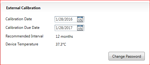
In MAX, there is a field for 'Calibration due Date', but 'Get calibration Information.vi' in the library of VirtualBench isn't an exit for him. This value is available by adding the date of calibration and the interval?
Of the API VirtualBench, Yes, you must build the next date of calibration recommended since the last date of calibration and calibration interval.
You can also get recommendations next calibration date using the API of the System Configuration. There is an example that illustrates this in Finder example: material input and output-> system-> Calibration Audit.vi Configuration
-
VST: entered password for calibration of VI
Where do we get the password, which is a string input required for the screw for the VST calbration?
The default password of calibration is 'NOR '.
-
Can I synchronize list XCP DAQ with my analog input data data?
Hi all
"I use ' ECU M & C" for measurement of a computer data using the XCP DAQ list. "The data is read at the sampling frequency I put in ' MC DAQ initialize.vi. This works well.
I want to associate this data with my DAQmx device measures. Is it possible to synchronize the clocks of the sample (by RTSI?) in the same way, it would be with DAQmx CAN synchronize data?
Material: NO PCI-CAN/2 & OR PCI-6229.
Thanks for any input.
PJ
Hi PJ,.
Well, I think I understand now, I don't know why I DINA see this before. It is not possbile to do this with the ECU Measurement and Calibration Toolkit, sort of XCP DAQ, is not something that you are able to do.
Best regards
-
How NI PCI 4474 DSA detects an overload to the input channel?
I read "Manual user OR dynamic signal acquisition." It is written that NI PCI 4474 support only digital overload detection.
Here's my question. What is the detection of digital overload? If an analog signal is already converted to digital signal, it can not be signals exceeds the limit. Or the DSA may already be damaged during the CDA process, if there is surcharge from the input signal. Thank you.
Hyun
Yes, the chip has more information about the Board and apply factors of calibration, which is how it can overflow.
What we call "detection of overload analog domain" requires more equipment (i.e. a comparator circuit) to observe the input signal. Given that the Committee in question is not a comparator to check the input signal, and the way we want to give the user an idea of whether or not their signal is too large, we simply use the mathematics inside the chip. It's better than nothing.
Oh, and I should mention that the protection is managed by a completely different circuit. The specification should say how much voltage you can apply to the Commission before the protection comes into play.
Germano-
-
cDAQ 9171 verification of the calibration
We try to evaluate the verification requirements of a single 9171 locations USB cDAQ chassis calibration.
We use a cDAQ 9171 to take some simple +/-5 volts using an analog input module 9205 readings. The 9205 has a specific calibration and verification manual for voltage measurements, no confusion there at the moment.
This article has a general verification for cDAQ chassis process that focuses on a digital input module. Is this something that will affect the analog voltage signals, we'll pick up? Is there a way to check the calibration using the module, we already have? Or is the calibration process 9205 alone that relate to our simple tension collection installation?
The calibration of the frame is reserved for the digital I/o. This is why I do not think that this will affect the readout. Calibration of the module must be the only one that applies to analogue tasks.
-
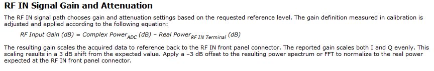
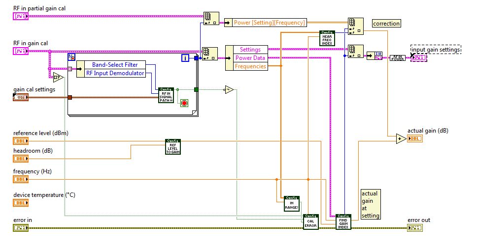
Vst 5645r PXI gain / attenuation calibration chain RX TX
Hello
I work with PXI vst 5645r. I did some research using the RF output of the transmitter connected with the receiver RF input.
In my application, it is important to know the equivalent mitigation and win I get (output of the DAC) generation up to the acquisition (input of the ADC) (loop gain).
I looked at http://zone.ni.com/reference/en-XX/help/373680C-01/vstdevices/5645_analog_input/ and http://zone.ni.com/reference/en-XX/help/373680C-01/vstdevices/5645_analog_output/ in order to better understand how to build the structure of my channels.
Whole, I looked in the drawing in labview how these parameters are controlled and value (example VST streaming (host)). I found only the configuration of gain for the transmitter in the 'LO_cal' block but I don't see no calculations for the various mitigations of transmitter. I have to check these datas for the transmitter.
How are managed and put all these settings in the transmitter and the receiver normally?
I guess that the receiver channel attenuates the signal in order to use the dynamic maximum range od a/d converters and use good power from receiver... calibration changes the values of gain/attenuation in the receiver string whenever I use a different gain (peak power dbm) of the issuer?
Thanks in advance
Best regards
Giuseppe
The reference level is a 'guide' for the driver VST set the attenuators and win as well as the range of the ADC/DAC are used at best.
Depending on the frequency that you and the chosen reference level, the VST pilot will focus on the best combination of the mitigationsand win to get the Signal arriving at the ADC to use his full range:
You can see the calculations in this niRFRIO Group A Config 1.0.0 Shared Private.lvlib elect RF calibrated Gain.vi
This Gain is 'Gain of frequency step-down converter' that summarize the entire path of Rf In.
So practicall frequencies/Upconverter Gain step-down converter is the total analog gain that is put on the signal just before and after the ADC/DAC.
This is done in the niRFRIO Group A Config 1.0.0 Shared Private.lvlibelect RF calibrated in Gain.vi.The discovery to Gain Index scan all possible power levels for this frequency and get the level closest to the chosen reference level.
Whith this information, he knows what attenuators and win it must reach the power to get at its best at the ADC (input gain settings)
So to calculate the loop gain, you must define a level of refeerence fix so that all mitigations and gain in the two paths of remain fixed, test it with a calibrated CW and then use this configuration for your DUT.
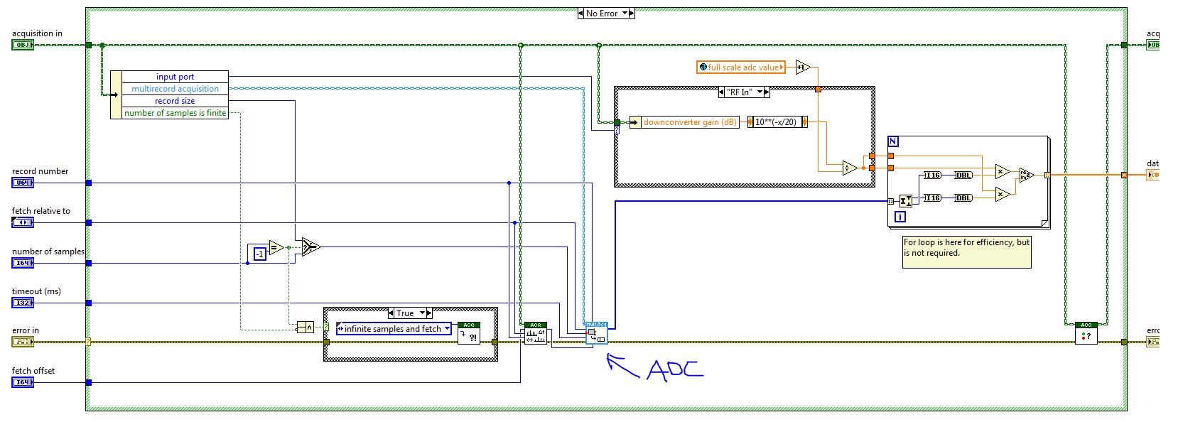
When you read the QI of the VST (retrieve a single record) this information is passed to the function, so it can calculate the values of CDA and calibrated to their actual value on the RF In:
If you calculate the gain of loop inside the FPGA, then he must send the information of step-down converter frequency/upconverter gain between the host and the FPGA. You can then use this information to calculate the loop gain.
Best wishes
-
analog calibration on PCI-6221
I don't get the volts per bit, I expect my Board of PCI-6221.
I run the "Test Panel" available in v.4.3 Measurment & Automation Explorer. I have a NOR-6221 multifunction with an installed interface BNC-2090 case. When I run the "analog input" test, with entries dfferential and connected to ai8 ai0, I expect to 0 volt. The input values, the min max run defaults to-10 V + 10 V. The graph shows zero + - 1 to 2 bits of noise. See screenshot. The reported real amplitudes are + 0.000468, + 0.000144, - 0.000180, - 0.000504. This corresponds to 0.000324 V/bit. I expect to 20V / (2 ^ 16 bits) = 20V/65536 bits = V/bit 0.000360. How to explain that gap of 10%? Thank you.
Bill
Hey Bill,.
I could see a few things: with the M series, realize that the data returned by the ADC are not linear, so that V/bit varies over the range of the acquisition. Mcal allows us to correct the non linearity. Which may explain the discrepancy just here. Also note that the range is actually greater large - to make cal the range desired, some codes are outside the range of V 10 - generally of 5%. However this would actually push the V/bit upward. This is mentioned in the M-series user manual in the section of the analog input range . All this is taken into account absolute accuracy specifications so that they are still valid.
Finally, when I calculate 20/65536 I obtiens.0003052 - which, once I multiplied by 1.05 gives moi.0003204, which looks a lot better. You may have swapped the 6 and 5, or the Windows calculator is fibbing to me once again

So this brings me to my question - you notice the difference just theoretical vs measured and I was wondering what is happening, or you plan the use of this info? If you are looking to read binary (a common practice results in questions like yours), take a look at this KB when you get to the scale of calibrated data-
3SKGA409 Ko AE: is raw data DAQmx calibrated and/or scaling?
Hope this helps,
Andrew S
-
Is it possible to copy the data from claibration from VI to another or a DAQ Assistant to another? I have calibrated pressure in separate Vi sensors and now want to create a handset. While the scales are calibrations are not. However has no way to insert the calibration, short data to get a voltage generator and recreate all the tensions. Use the table across a reasonable alternative?
If you press pause within the calibration tool, you can change the input value and the reference and then validate them both, so problem solved.
-
NI USB - 6212 BNC analog input impedance matching
I just ordered a case NOR USB - 6212 BNC DAQ (should be delivered soon). I want to use to measure HV signals using a probe of high voltage of 1/1000 I have.
Now, datasheet of the probe (not a lot of info) says it has an impedance imput 100MOhm. I suppose that it consists of a simple resisitve divider, and if the ratio is 1/1000, I wait so to have a 99.9MOhm resistance in series with a 0.1MOhm resistance. However, the data sheet also specify that the probe is designed to be connected to an oscilloscope with an impedance of 1MOhm. As this input impedance is very low compared to the low value of the separator of resistance resistance, so I guess that the real resistance at the level of the sensor values 99.9MOhm and 0.11MOhm (to obtain the 0.99 and 0.1MOhm when it is connected to the oscilloscope for 1mW).
Therefore, given that the impedance of the USB-6212 according to the datasheet, the analog input is > 10GOhm, I expect to measure higher to true alternative voltages when connected to the acquisition of data from 10%. This assumption has a meaning?
What would be the best way to get around this? Do a calibration and correct the values acquired in LabVIEW code? Or should I add precision 1MOhm resistance at the same time to the acquisition of input data to decrease its resistance to entry to the value expected by the probe?
Thanks for your help!
Since you have a range of 1000: 1 I guess you also need bandwidth (I have a TEK 6015 A
), so you need based on the impedance input, a complex value, means he must not only watch but also the ability to input resistance (1 M). demarcation of the field probes have usually some elements of toppings to match the probe and the input scope. RTFM of the help of the probe
BUT a more serious point is that with your probe, you have a very high resistance. And if you look in the specification of the 6212 you will find on page 2 by mistake ppm in logarithmic scale graph! and even 100 k source impedance it not shown.
So I'm afraid that a simple 1 M on the DAQ entry can work if you're only measuring DC, and only if you use a channel on the acquisition of data. A workaround is an amplifier separate buffer with an impedance of good entry corresponding to the specification of your probe and a low output impedance.
-
The measure of multi-lane thermocouple simultaneously via 9213 (with USB 9171)
I'm just back in Labview after 10-year absence. My first goal is to measure thermocouples of Type J and T with a 9213. A 9213, 16 channels, but the screw example I found so far allow only a channel be selected at a time. Ideally, it would be good to have the option to select among the 16 tracks to read at some point (that is, any combination of 1 to 16 and channels jump if necessary).
Secondly, multiple channels for simultaneous playback selection will affect the sampling frequency? For example, if 10 samples can be read per second, and selects 16 channels, does it take 1.6 seconds for all read? And what happens if I put the sampling rate of 1 second in the previous example? It keep track of cycles "planned" and keep running unfinished loops after that I have to stop?
Thirdly, I don't understand whether it is possible to assign a different thermocouple for each channel type. Can I combine thermocouples of Type J and T on the same card? Is the case, then how to set each channel individually?
Fourth, I met error readings when you select a channel open to the VI for the 9213. Is this normal? Ideally I would like to be able to Exchange thermocouples during continous measurement and worry that the program will crash.
Example of two screws, I found are: "Input.vi Thermocouple - continuous" from the Finder of example of OR. The other is spent by the sample project "continuous measurement and logging (OR-DAQmx)."
-
The PCI-6132 analog inputs does not
Hello
I have problems to install a PCI-6132 card on one of my computers. I am runing Labview 7.1 and DAQmx 8.6. In MAX, I opened the unit and test panels. The counters are working fine however the analog inputs always give v - 10 (-5 If the a - 5 min) without noise. the same on each channel. I have not connected any termianls and expect to see the noise around zero volts. In addition, the card fails the error calibration auto-200545.
I took an another PCI-6132 of a system works in this computer and had the same problem. So I guess the problem is the configuration of the computer or software. I try to reinstall the DAQmx and labview and the problem has not been corrected.
Nick Wagner
NOAA/ESRL/CSD
(303) 497-3924
-
NEITHER 9213 working with 9174 DAQ for reading of temperature
Hello
I use NI 9213 and DAQ-9174 to monitor the temperature. Without thermocouple wire connected, using NOR-DAQmx tasks, reading is 2.296334 K. When I use DAQmx Read (Analog DBL 1Chan 1Samp) .vi, reading is 1377.69.
1. What is the good?
2. why reading is not taken into account the room temperature which is around 26?
3. do I need to do the calibration for NI9213 before using it?
Thank you
Ott
Hi Ott,
If you do not have a thermocouple attached to the 9213 module, the module just go read electric noises. This electrical noise has no physical relationship to the room temperature. When you do actually connect the thermocouple, be sure to configure the DAQmx task as a task of thermocouple to HAVE. Also be sure to select the correct thermocouple specifications (i.e. type of thermocouple).
Here is a good article giving measures by thermocouple.
Here is the acquisition of data getting started guide.
Hope this helps,
Chris G

Maybe you are looking for
-
My old themes do not work with this version of FF.
On the latest upgrades FF bit the themes available considerably decreased and now the majority of my registered themes said "not compatible with this version of FF. Whyzat?
-
How many tabs can be defined on a page
How many tabs can be defined on a page
-
my hp DVDRAM GT31L ATA Device stopped working tried to reinstall the driver by using Device Manager, but it installs not says windows cannot start this hardware device because its information of configuration (in the registry) is incomplete or damage
-
I have a new printer HP 8100 pro. I'm trying to print labels Avery 5428 with pictures on it. It is a Matt appearance and size of the small sheet of 20 labels per sheet 4 x 6 inches. My operating system is Windows 7 and I use MS Word 2007 with the
-
Impossible to reinstall Windows 7 after installation of 10
I installed Windows on my laptop 10 knowing that it was a bad idea. And of course it soon to my 7 back. It's a joke. I tried for 3 days and nothing works. I get messages like this application can run on your pc. Really, but it came with this before t