NEITHER 9215, 9263 analog operations
Hello
I'm doing a simple entry that and power: I generate the signal using a Tektronix (30 Hz, 2 V p - p) signal generator and consider it as an analog input of 9215 using DAQ Assistant-1. Multiply by 2, and then send it as an output analog by 9263 using DAQ Assistant-2. Later, I see this singal on an oscilloscpoe. Here are the settings for the acquisition of data Assistants:
Assistant DAQ-1:
Mode: continuous
Price: 1 K
N ° of samples: 1000
Clock type: internal
Assistant DAQ-2:
Mode: continuous
Schedule use of waveform data
Clock type: internal
When I run the VI, it stops after about 25 seconds, which gives the error:
Error 200279 occurred at DAQmx Read (analog 1-d Wfm NChan NSamp) .vi:1
Attempted to read samples that are no longer available. The requested sample was already available, but has since been replaced.
Increase in the size of buffer, most frequently the reading of data or by specifying a fixed number of samples to read instead of reading all available samples would correct the problem.
Property: RelativeTo
Corresponding value: current playback Position
Property: Offset
Corresponding value:
Task name: _unnamedTask<6>
Why are they bad?
By test error, I found that by the acquisition of data Wizard-1 mode to "N samples", I was no longer getting this error. However, then a big delay time has been introduced. that is if I change the frequency of the signal (say 15 Hz to 30 Hz), then this change is reflected on the oscilloscope 10 seconds later. Why is this happening? And how can I solve it?
I enclose the dig that for reference.
Thank you
Mandar
Hi Mandar_K,
Thanks for the reply and I hope that your well today!
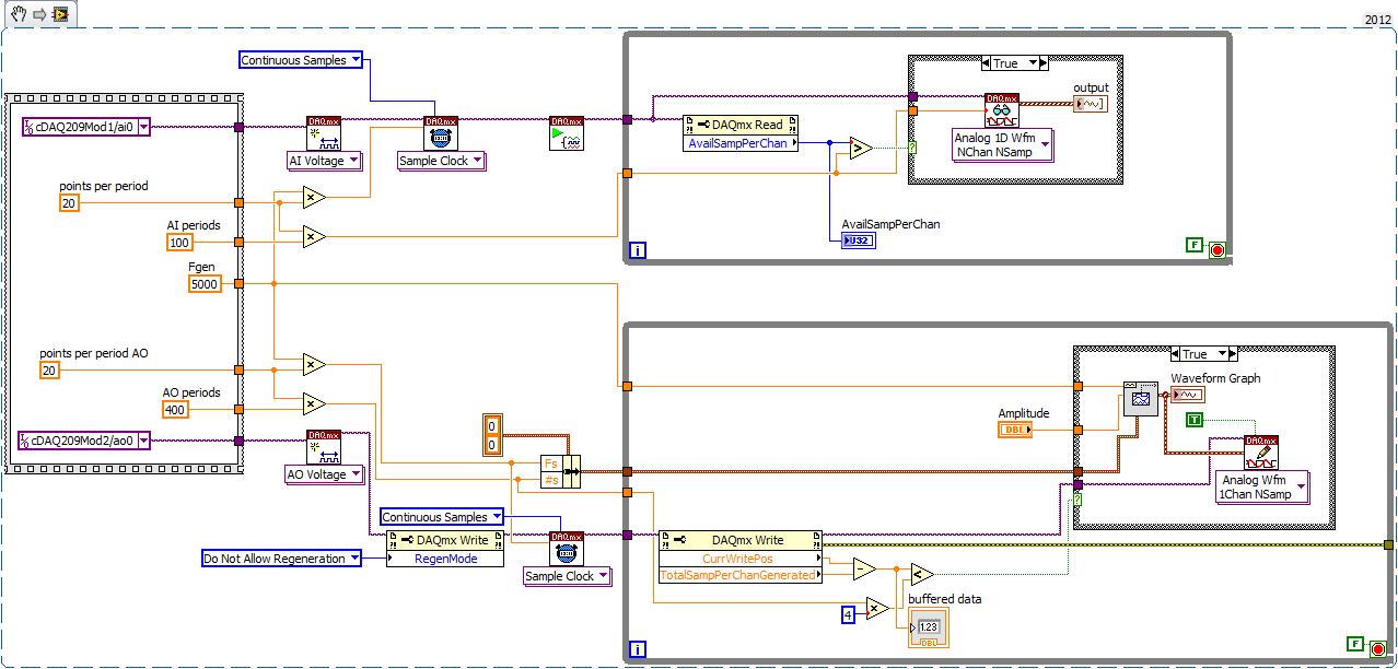
It is an example that I did with a synchronized AI read, some treatment, then AO. This seems to be what you need.
If please take a look (LV8.2) and let me know what you think,
Kind regards
Tags: NI Hardware
Similar Questions
-
CDAQ 9191 or NI 9215 there a fpga module that we can program?
Is it possible to perform mathematical operations with the signals that we gain by using cdaq 9191 and NI 9215?
Once the 9191 is set up in MAX, you can read the channels on the 9215 and do what you want with the data. The 9191 is used only to transmit data from the 9215 on a computer that is running LabVIEW, where you can perform mathematical operations.
If you want or need FPGA, you get a compact chassis of RIO, not a compactDAQ chassis.
-
NEITHER 9215 delay in phase between two channels
Hello
I use Ni9215 with ENET-9163 to measure the phase between two sinusoidal incremental signals delay. First signal connected to AI0 and, secondly, to AI4 at 100 k sample rate. I know 9215 simultaneous ADC, but it seems to me that NI 9215 gives additional time between the channels. Is it possible, or l mistaken?Alexandr.
Hi Alexander,.
Please let us know how you get on,
Chris is correct - with the idea of using a right signal to both channels, I tried to suggest this earlier...
I hope this helps with your problems with delays,
-
NEITHER USB-6343 analog and digital grounds
In the manual for the NI USB-6343, it is said that the mass input/output, analog and digital terrestrial are related, but by a small sign. For my application, I am attaching all 3 these grounds to exit the box (I'm tie all areas with physical threads). It is perhaps a silly question, but it's OK to do, correct?
This should be OK unless there are large currents flowing on ground conductors. If you have important currents in the ground, you have other problems that must be resolved before you connect the DAQ hardware.
Lynn
-
Bad analog output help Every_N_Samples-NI-9263 cDAQ-9172 chassis (works with cDAQ-9178 chassis)
Hello
The NOR-9263 analog output voltage geberation works correctly with the cDAQ-9178 chassis but gives wrong result using the chassis NOR cDAQ-9172.
In the attached code example, a single cycle of a sine wave is composed of 40000 samples and came out in the background using Every_N_Samples at a rate of production of 5000 samples per second.
The output buffer size is set to 10000 samples.
Prepare us the buffer writing 10000 samples 1, then write the remaining data in the background using the Every_N_Samples callback.
Bug: Using the cDAQ-9172 chassis, to the 5000 s/s sampling rate with the help of an external field (or through closure to another HAVE), we observed that 1 10000 samples came out twice, followed by the rest of the waveform. The last 10000 samples are never exits. If you are working properly, we would expect to see 1 full cycle of a sine wave.The bug does not occur with the chassis NOR cDAQ-9178. I use the driver NIDAQmx v9.2.1f0 on Windows XP
The bug does not happen with simulation devices, so you will need to use harwdare real to reproduce.Please find attached an example of code C based on the example program OR "ContGen - IntClk.c" to reproduce this bug.
Thank you
whemdan,
The MathWorks
Hi whemdan,
By default, DAQmx regenerate old samples if no new data is available. To give the correct behavior, you can:
Use DAQmxSetWriteRegenMode to disable the regeneration (DAQmx_Val_DoNotAllowRegen). In most cases, this is recommended if new data are written continuously in the buffer as the build is in progress.
If you just need to generate 40 k samples, you can write them just all at once, rather than in 10 pieces of k (the code you attached probably is just an example, so I'll assume that you have a reason to write the data into segments in your actual code).
I think the difference in behavior between 9172 and 9178 can if explained by the different way, buffering is set up on each product. The 9172 uses a buffer of 8 k (on the STC2) in all cases (source). The 9178 uses an 8 k of memory buffer (on the STC3) If you use regeneration shipped, but uses the 127 samples FIFO cartridge, if you use no on-board regeneration (source).
Then... on the 9172 8191 samples are immediately transferred to the FIFO. By default, the hardware is going to request new data when the FIFO is less to fill (this is configurable with DAQmxSetAODataXferReqCond). I'm not sure what the transfer data request size is in your case (you can set the maximum value with DAQmxSetAOUsbXferReqSize), but obviously it is bigger than the other 1809 samples that you have not yet sent to the Board of Directors of your first entry. At this point, the pilot will regenerate 10 existing k samples so that sufficient data will be available to meet the demand of data transfer.
The 9178 however use the FIFO of 127 smaller samples so you will not have the same behavior in your case.
In summary, the behavior is explainable by the difference of material. If you want to avoid to regenerate old samples, you should ban the regeneration using DAQmxSetWriteRegenMode.
Best regards
-
How to speed up loop DAQ triggered using NOR cDAQ-9174 with NOR-9215 and NOR-9402
Hello
I use LV2010 and NOR-DAQmx 9.2.2. I have a NOR cDAQ-9174 with a NEITHER-9215 4 channel 100 k simultaneous ADC and NOR-9402 4 channel DIO module trigger and reset.
We run WinXP sp3 on a Dell M4400 core 2 duo @2. 26 Ghz.
I used the code example NI DAQmx for acquisition of tension with trigger HW. My goal is to try all 4 channels on the 9215 simultaneously when a trigger is received on channel 0 of the 9402, after data is read, I use channel 1 on the 9402 to reset the trigger of the target material. I have a version of this work, however the maximum event rate is ~ 16/second. I have the Setup 9215 for finite samples / 10 samples per channel which is ~ 400uSec of conversion time and I realize he is above in the appeal of vi, but ~ 50mSeconds worth?
The target detector can put out up to 1 k / event triggers / seconds. Only, I received a rate of 8 per second and I added the NOR-DAQmx control vi driver and chose "commit" this did double the rate.
My question is what is the maximum rate of loop for these devices (trigger/conversion/reading device / reset) and start over? I noticed that just let free the 9215, carried out using the 'Acq & chart internal strain Clk' raised only the rate of events up to 20 Hz.
Thank you
normbo663
Hi normbo663,
You can get this works far better assuming you have an available counter (there are 4 on the backplane of the 9174).
DAQ Compact supports the tasks of meter output "redeclenchables" that can be used to generate a finite pulse train. You can set a task of finished meter redeclenchables output to be used as sample for your task of analog clock. The task of the meter output will be re-Army (less than 12, 5-25 ns) as soon as it's finished out the last pulse. The task of analog input would be configured to run continuously, but it would only sample based on the output of the meter triggered. For an example, see here.
You can reference the internal counters on the cDAQ without signals through a routing module using: cDAQ1/_ctr0 (right click on the chain counter control, then select i/o name of filtering and check channels internal to add these options to the drop down).
Thus, with the tips above, you should be able to immediately re - arming your analog acquisition on the 9215 using one background basket counters. It seems that the second half of the application is to use a second channel on the 9402 to reset the trigger of your DUT. You can deterministically generate this signal so by configuring a 2nd redeclenchables meter out task (single pulse, but this time). All you need to do is the initial delay on the appropriate value for your analog acquisition. Trigger this counter on the same PFI line that trigger you your analog task from.
Using counters to generate the signals you need in a deterministic way, the loop becomes is no longer a problem (as long as your input buffer does not overflow). You may need to re-read several triggers at the same time for the loop to keep (for example to read 1000 samples each, which would correspond to 100 triggers 10 samples).
Best regards
-
Hello
I have a question about the resolution of the NOR-9263 analog output module.
The specs say it's 16-bit resolution, and that it has a range of 20V (-/ + 10V). I want to use the NOR-9263 to reproduce a 16-bit recording of a waveform, but I need the output of 0V to 1.2V.
I have 2 choices:
(1) use LabVIEW to scale my signal to be between 0 v and 1.2V, before sending it to the NOR-9263, or
(2) send my waveform to the NOR-9263 (taking advantage of the full range of 20V), mitigate and pass level DC using basic op-amp circuits.
I think that option (2) is better, but I want to check my reasoning in this forum.
If the resolution of the NOR-9263 is 16 bits, which corresponds to 65 536 different voltage levels which can be represented. I'm assuming it's on the whole of the party, if the device can generate pressure separated by 300 uV (= 20/65536) levels. Now, if I had to tighten my waveform in a 0-1, 2V rank, which is the option (1), I'm assuming this corresponds to only 4000 (=1.2/0.0003 about) of these voltage levels. It is roughly 12 bits, which means that I would essentially lose 4 bits of information of my waveform.
Using option (2), I would get a voltage analogue output with 16-bit resolution, and no information would be lost my waveform. The downside is that some external circuits are needed for mitigation and offset level.
I was wondering if this reasoning is correct. On the other hand, it may be true that the unit fits when you specify minimum and maximum levels of voltage (via the '.vi DAQmx create channel (AO-tension-Basic)'), so that the voltage levels are separated by less than 300uV (in my case, I need ~ 18uV separation to achieve 16-bit resolution on the beach 1.2V).
Best regards
Robert McEvoy
Hello Robert,.
You are correct that your range of adjustment with 0V - 1.2V will not increase the size of your possible step. The NOR-9263 has an input range, so you will need to go with your external hardware option if you need hold the 16-bit resolution. Please note that if you should also determine the accuracy specifications given in the detailed specification document to determine possible inaccuracies in generation of the NOR-9263.
Kind regards
-
Hello guys,.
I have a general question regarding the units of packaging such as the USB-9263 analog output signal. If I can use it instead of data acquisition to provide an analog voltage output?
Thank you
ELA
Yes, the 9263 can provide 4 output channels analog voltage (+/-10 v range) with up to 1mA of current drive. Looks like: it refers to the short circuit of conditioning of signals and some protection against overvoltage. Link below is the User Guide:
http://www.NI.com/PDF/manuals/372406b.PDF
-AK2DM
-
Configuration of the basic Source of time to master for the 9234
I have several cDAQ modules I use to collect data. I use vi to Write can Express to save data to a file of PDM.
When you examine the recorded data files, the measured data from NI 9215 provide pleasant timestamps to match how the DAQmx task has been set up--delaying the sampling frequency of 1000 with a 1 ms in the While loop. However, although in the same vi - different tasks, but the same while loop - horodateurs of the NI 9234 do not correspond to the task of DAQmx implemented - sampling frequency of 1000 with a 1ms delay. After reading the material provided with the NI 9234, I found that maybe the machine clean master Timebase Source. There were documents that says he can be configured to be originally of Timebase of Master for the other modules:
Configuration of the basic Source of time of the master for the NI 9234 (Interface FPGA)
It is desirable to have the timestamps for data measured across all modules to match. We do not have the FPGA Module for LabVIEW. Is there a method in LabVIEW for all modules use the same master time base Source? I assumed that because all the data collection has place in the same while loop by using the time delay of 1 ms it was forced through the code. This hypothesis seems incorrect from my review of the PDM data files.
The NI 9204 provides a trigger only.
Software:
Windows 7
LabVIEW 2010 SP1
Material:
CDAQ-9174 chassis
Slot 1: NEITHER 9204
Slot 2: NEITHER 9215
Slot 3: NEITHER 9234
Slot 4; Vacuum
Hi MgDAQ,
An important concept to note is that the 9234 uses a delta-sigma converter and a clock of oversampling to read analog data. There is an inherent delay of entry due to analog and digital filtering built-in. Since the 9215 has a lower resolution there will be a lag the 9234 and 9215 finished. I've included some resources below:
What are the for the NI 9233, NI 9234, and NI 9237 valid sampling rates? : http://digital.ni.com/public.nsf/allkb/593CC07F76B1405A862570DE005F6836?OpenDocument
Synchronization of DSA, S and X series devices with a NEITHER-DAQmx single task series: http://digital.ni.com/public.nsf/websearch/78E44565FD87E7D686257108007F94F8?OpenDocument
Synchronization with NOR-DAQmx of acquiring dynamic signals (DSA) products:http://digital.ni.com/public.nsf/allkb/A133ED27DF9BCC5986256F2E004BA342?OpenDocument
Have you tried to put two modules in the same spot? Alternatively, you can export the sample clock 9234 and tasks installation separately.
Best,
CARISA
-
Hello
I 9184 cDAQ chassis with two modules installed: NEITHER 9215 (HAVE) and NI 9263 (AO).
AO generates the signal of 5 kHz and bought it. Initially, all right, but after 20-30 seconds, it has delays (up to 30 seconds!) between the production and acquisition.
Time lag depends on the speed of the DAC. If it 20 * 5000 = 100 kHz, delay = 15 sec, if it 10 * 5000 = 50 kHz, the delay is 30 sec.
It works with the PCI - DAQ version, but I do not understand why he has these delays with ethernet chassis.
I tested it on gigabit ethernet with chassis directly connected to the host. But I don't think that problem is on a network, because the net charge is 0.55% and ~ 1Mb\s data transfer. The processor is also low.
And I think evil isn't in the generation, acquisition, as it evacuates all samples in buffer (number per channel in DAQmx read nearby 'availsamplesperchan') and because changing CAD rate influence on signal updates.
In addition, it works fine without these big delays to signal lower rates, for example, sine wave 50 Hz generating.
Example of code is to join. I read 100 times of 5 kHz sinusoid, 16 points per period (refresh rate = 80kHz, 1600samples). And 5 kHz sine generation of 100 periods with 20 points per period (rate is 100 kHz, 2000samples).
Now, this works in two separate loops with the control "TotalSampPerChanGenerated".
Problem was with a buffer too small mailing to cDAQ. 8 k samples and 4 caching works pretty stable buffers.
Also, I checked the difference between 'CurrWritePos' & 'TotalSampPerChanGenerated' and the maximum value is 1 500 000. 1 sample is it DBL, it really means that the buffer size is 1.5 M * 8 bytes = 12 MB.
Thanks for the thread.
-
Problem installing software in FPGA
Hello
I bought an FPGA (9074).
Following the help to get it runing it says I need to install the software using MAX.
The device was found in MAX, the network configuration works.
Right click on 'software '? "" remote systems "to add the basic software for operating the unit.
I only get the first option (OR-RIO 3.1.0 minimal, January 2009), the others are grayed out, so he ends up with not a lot of functions in Labview to develop my program, I have no serial communication or the PID function for example.
I'm using Labview 8.6.1.
I have the module 9263 (analog output) and his work very well with the 9074.
What should I do to be able to install a more complete set of software outside the minimum?
Sandro
Problem solved, any new, OR just last installed device driver.
Thanks for the reply.
-
Hello
I have the following hardware configuration:
-compactRIO controller 9074 with NI 9505 (DC Brushed Servo Drive) and NI 9263 (analog outputs).
-Maxon Motor RE 40 (no-load speed ~ 7500 RPM)
-R137 encoder Gurley (180000 cycles/rev = 720000 counties/turn after quadrature)--> signal of the encoder is connected to the NI 9505 motor on the specific slit for encoder control.
The problem that I face is that the NI 9505 module cannot detect speeds greater than about 1 130 RPM. I tried with a much smaller resolution (2000 counts/rev) encoder and it works fine. It seems to me that somehow the resolution that the NI 9505 module is read in the indictment is not big enough or something similar. Someone has a similar problem? What are the exact specifications I should look in the technical sheets to try to match the resolution of the encoder with the resolution of the map?
Thank you
Bogdan
Hello Bogdan,
Please take a look at the 'NI 9505 Operating Instructions and specifications' (http://digital.ni.com/manuals.nsf/websearch/8F6DCAB89D6B9BAD862576850075EA18). On page 29, you'll find "Entry Encoder features" the value of "Maximum quadrature frequency". This frequency is for the NI 9505 f = 5 MHz.
Kind regards
Johannes Graeper
Technical sales engineer
National Instruments
-
CVS1458RT, EtherCAT 9144, Softmotion
Hello
I just wanted to confirm.
I want to use a 9263 analog output and a diff 9411 channel installed on a chassis of 9144 EtherCAT.
I want then to use a CVS 1458RT and loop Softmotion RT to control those. (similar to the example: Interface for servomotors (9263 & 9401 & 9411))
The difference is that the EtherCAT FPGA o not available as in the example.
Is is possible? How? Using User Variables instead of the FPGA-defined reference node to write property?
Thank you
Patrick
Hello
Finally, by replacing any reference FPGA by the user-defined variable, everything works fine.
I replaced all references at the same time, FPGA VI and VI RT with the user-defined variable.
Thanks for help.
-
Is it possible to measure digital signals with devices of simulations?
The simulated device configuration is the following:
9174 chassis cDAQ (cDAQ1)
-9215 (cDAQ1Mod1) (analog in)
-9401 (cDAQ1Mod2) (digital i/o)
With a digital line (e.g., line 4), I create a single pulse
------^---------....
where the circumflex indicates the pulse short and simple.
Is it possible to use a digital line (for example, the line 0) in to measure it in the device simulated using a kind of direct/indirect routing? If so, how a set to the top of the digital input read task essentially read the output on line 4, internally?
Thank you.
N ° as the DAQmx help explains, you do not have this ability with a simulated device.
-
Poor quality with cDaq sinewave output
I have a cDaq 9174 with 9263 analog output module. As part of a larger system, I try to create a sinusoidal signal generator but have big problems getting something like a reasonable waveform.
I use the express VI the sinus sumulate, then in the service of analog output of DAQ assistant and just feed of amplitude and frequency values in the sine function.
Above about 50 Hz, everything works well, but 50 Hz 0.1 Hz (the range I need to use) the waveform is terrible, not sinusoidal and sometimes cut off upwards. Possible combinations tried as much as I can think of for settings of the sine and the analogue output function, without success. I contacted OR this topic and they executed my VI and say it works very well. but they do not have the same material as me to try it. I have two lots of material and the same problem occurs on both, so is not a defective hardware problem.
I use an external oscilloscope to measure the waveform and we tried two different units, with the same results on both.
Maybe you are looking for
-
Equium l20-198: what battery model is compatible
Having bought just an Equium l20 - 198 I'm horrified to find that the battery (2000 mAh) dies in less than an hour. It's quite desperate and it is almost impossible to get a decent job done use away from a power outlet. I have yet to find a 'battery'
-
Hello world I am new to labview and was hoping if someone could help with a fundamental question. I have to do a program that checks the capacitors, the program uses a Velleman K8055 or VM110N card. I try to give is short and simple: -Time measure. -
-
I think my question speaks for itself. I don't need answers on windows 7 so quit trying to sell all his chances. I am looking for information on computer remotely with windows xp and all I get are answers to problems with windows 7. I want to acce
-
Windows Vista Edition Home Premium BSOD "Bad Pool Header" Help!
I can't not understand how to solve this problem, I searched everywhere on the internet and I tried solutions told me, I don't know if I have done wrong or what, but please help me. If I can't understand that this point I will be without a computer u
-
some of my maintenance tools do not work
My programs in my ADM tool does not work please help...