Nominal current PCI-7813R 5V Terminal
What is the maximum load for the terminal 5V on the connector 0 of the PCI-7813R card? What is the amperage of the fuse of the Council?
Yes, this A 0.5 limit applies to pins 27/28 (+ 5V) connector 0 on the PXI-7813R system.
Tags: NI Hardware
Similar Questions
-
Maximum nominal current of the + 5V terminal in PXI-7813R
Hello
I'm a little confused on the maximum nominal current of the + 5V terminal of PXI-7813R in 'NI R Series multifunction RIO specifications '. I understand that there are four connectors for PXI-7813R and each connector has two terminals of 5V +. If I use this + 5V to power my external circuit, what is the maximum current that can be supplied by each terminal?
Thank you
Gwenaëlle
I got your point, in this case I can do separately.
Thank you
Gwenaëlle
-
Windows 7 64-bit PCI-7813R compatibility & PCI6225 cards.
We have a desktop PC that works under Windows 7 (64-bit). Labview 2012 64-bit version is compatible with
PCI-7813R & maps PCI-6225?
There is no 64-bit versions of the FPGA or RT modules at this time. The interface LabVIEW FPGA host does support 64-bit, but it's just to interface with the target once a bitfile has been deployed and does not allow you to create a new 64-bit LabVIEW bitfiles.
So, if you are doing development on this machine, you must use the 32-bit version of LabVIEW (works great, even on x 64 OSes). Your hardware all still work no matter what. I just wanted to be clear that for development, you should use the 32-bit version of LabVIEW when working with modules FPGA or RT.
-
Hi, I use a PCI-7813R and cards PCI-6225 and I would check if the MASS D, GND AI and AO GND are connected to the chassis/building land. Thank you.
Hi Napoy,
For cards, AIGND, AOGND and DGND, all are connected internally to the chassis ground (which, if plugged into a properly wired outlet is connected to a building plot).
This is confirmed in these two articles:
How are the various related grounds in an R Series device?
http://digital.NI.com/public.nsf/allkb/1670D0423F6A123E862576EB0070D63F?OpenDocument
Are the ground on my DAQ devices all tied together?
http://digital.NI.com/public.nsf/allkb/02A451C0A88A3EAE8625702F0059C98E
-
OR PCI-7813R is recognized as PCI-7811R
Thanks a lot for your help intend. I found the solution. It was the mistake in our laboratory. I used the wrong advice. It was really 7811 I had in my PC. Map right (7813) was on the set.

Life is funny, but sometimes we lose a lot of time and resources by mistake.
Thanks and greetings
Artur
This task should be now closed.
-
HP pavilion p6754y: is the slot on my motherboard 1.0 or 2.0 pci
Hello
I searched many forums/Device Manager and you can't get a solid answer on whether or not my pci port is a 1.0 or 2.0, I'll replace my current video adapter with one that is 3.0 and I'm not sure whether or not to upgrade the mb with the gc. And if my current pci slot is 1.0, even it would be necessary to upgrade for the 3.0 gc?
Thank you
Statik, welcome to the forum.
This is the page for Specifications of the motherboard of the computer. She says she has "1 PCI Express x 16 slot speed Gen 2. You can use a PCI Express 3.0 x 16 into the slot of the Gen 2. They are backward compatible.
You need to upgrade the power supply (PSU), also. The current PSU is only 250W. Most new mid-level video cards require at least 400W to work properly. The last problem is, the new cards (EVGA 700 series for example) require UEFI in the motherboard instead of a standard BIOS.
Please click on the Thumbs up button '+' if I helped you and click on "Accept as Solution" If your problem is resolved.
-
PCI-E cards 2 verses 3 PCI-E RAID
Hello
I think buy one of the current areca 1880 6GBS sas cards Raid, they are as you know PCI-E 2.
As far as I can make out they use 8 channels, so there is no advantage in using a connector 16 tracks in my MB. (I think)
If they use fully all the bandwidth current PCI-E 2, so it doesn't matter how much forward to the Areca out later this year their 3 PCI-E?
Any thoughts would be appreciated.
All the best... Gary
PCIe 3.0 cards are not expected before Q1/2012 and perhaps even Q2. They will receive more recent chipsets in Q4 of 2011 at the earliest, so do your math.
The series of 1880 is indeed 8 x, but you can use a slot 16 x which will then run in mode 8 x.
-
HP pavilion m8100n: graphics cards
Hi there, you helped me a few weeks ago with my old office and your advice was helpful. It seems that my os I installed does not work with the nvidia graphics card in my machine insofar as there is no display whatsoever. After much research, I came to the conclusion that I need another brand of being well known for not being user-friendly linux nvidia card. Can you help me find a map generic compatible with this system? HP support no longer works with this model and when I try and buy video cards... well you probably understand this question.
Try an AMD\ ATI Radeon card or an older GeForce map. You need a card that has a legacy vBIOS. The vast majority of the current PCIe x 16 cards have EFI VBIOS.
Your best choice would be the second hand market, given the generation of your desktop PC is (year 2007).
A Radeon HD5750 would be a good choice.
-
External power supply for node 3202
Hello
I would like to design a solar energy system to the 3202 end node. But I'm not sure how to determine energy 3202 needs?
The external node power input is labeled with 9 - 30V, 2 w max. However, NEITHER provides funds (among to the 3202 node accessories) power which provides the power of 12 VDC up to 1.25 by 15 w.
If I use the 12V battery, that the current rating (or power) should be? 2W or 12V, 12V, 15W.
Thank you
Ahmed
I got the answer of the team of Technical Support OR Arabia.
Here is their response:
The 3202 node would be damaged if it takes more power of 2W. But when you connect a 12VDC with 1 battery. 25 a nominal current max, then the node 3202 draws much less current according to their needs.
-
Measure voltage across the thermistor outwardly excited
Hello
I'm looking to collect temperature data by measuring the voltage on an input temperature of a piece of industrial equipment terminal. A thermistor is currently connected to a Terminal, and my USB-6212 analog input terminal is connected in parallel. The equipment must remain functional, so the thermistor can not be deleted.
The problem is the USB-6212 disrupts significantly far - for example, the temperature of the equipment reading spikes of 45degF at 60degF whenever the USB-6212 is connected. Using a multimeter Fluke does not cause the same problem. I tried to measure the input impedance analog for the USB-6212 with a Fluke 87 - III. I get out of the range (> 50 M Ohm) with the lit 6212 and ~ 12 M Ohm in judgment. It seems to meet the specifications and should be high enough to not to disturb the measurement. I do not know the side of the probe, but estimate it's about 20K ohm based on measures of tension DMM with and without parallel resistances.
Can anyone suggest a way to solve this problem, or another way of measuring? The main constraint is that the thermistor must remain in the terminal of the temperature.
Thank you
Leo
Leo,
It's only a guess, but a guess a little.
Two clues: not measured with a multimeter is no distuirb the result. Measure with the USB-6212 disrupts the result.
The DMM is probably battery powered and not connected to any reference to the ground. Certainly, the USB device is connected to the USB ground which in turn is connected to the mass of the computer.
My guess: a ground loop between the acquisition of data/USB/computer and industrial equipment. Unless the industrial equipment specifies that one end of the probe is grounded and the reasons for the equipment and the computer are connected to the same point of mass, it will be difficult to measure as you described.
Things to try:
1. with the help of the DMM measure the voltage (AC and DC) between each end of the probe and the mass of the equipment.
2. with data acquisition/computer disconnected the measurement equipment (DMM), tensions between the computer or ground DAQ and the mass of the equipment.
3. If all the voltages measured in 1 and 2 are in the specification of common mode for entry for the DAQ hardware voltages, then try a differential connection with polarization adapted ground resistances.
Do you have a technical manual or diagrams for Brad equipment?
Lynn
-
Hello. I just got the Virtualbench and it has not evaluated with labview 2014.
For my system, when it is to the current around 6uA, sleep. On the asset, it attracts around 12mA. A multimeter using normal, it could be measured
Download the standard VI DMM of OR to test the feature.
Connect the virtual bench on the terminals of 100mA, because the measured current is lower than 12mA.
When the system is in standby mode, the VI reads consumption at rest as according
However, when the system turns on, it keeps displaying NAN and also the error message on over-range
Had attempted to remove the constant TRUE of the measuring range to configure DMM (VI) and feedingstuffs in digital constant 0.01, 0.1, he just posted the same question. Was even trying to feed constantly from 1 to 10 just to check the effect but it post the same question.
Grateful if you can give some insights on why is it so
concerning
Welcome to the forums and the platform NOR :-) How did you VirtualBench, LabVIEW and these forums?
Let me answer your questions.
ediva99 wrote:
The high nominal current value has to seems to be the lock at all about 700nA (negative values) that i do not understand why.This could be the noise in the environment since the terminals of the DMM are not shielded for noise. VirtualBench application has an offset function offset zero in the menu of the corner which allows the instrument noise.
VirtualBench specifications, page 9- http://digital.ni.com/manuals.nsf/websearch/C85FACB21C0B2E7586257D87007CF760
-
I have a question about a FPGA project I'm developing.
I use a digital RIO NI PCI-7813R, objective and Module FPGA 8.6.1
I implement a SPI bus, master.
I use a state machine in a single loop of Timed Cycle. (about model on one of your examples IP)
I'm running the loop at 20 MHz, which produced a clock of 10 MHz SPI bus data.
I send you the data in 8-bit bytes delivered by a FIFO of the host.
Similarly, I return data bytes of 8 bits of the host by using a different FIFO.
I have no problem sending data, generate all the select chip and data impulses on my desired clock edges.
It's manual clean and perfect as seen on a scope / Logic Analyzer.When I read data from i/o pin however I have found unexplained behavior.
It is this: the data seem to be trolling by two read operations.
When I read the axis of I/O data to the specified limit of the clock that I generate.
I found that the data were two bits shifted to the right, i.e., deferred, one on the scope / Logic Analyzer.
I did a work around by two pins I/O multiple read operations in time of the gap between the data bytes.
There are no generated clock signal and no data valid on the I/O pin at the time of these two read operations as testified to by the scope.
And now the data received matches perfectly to the one sent.
I can only assume that there is some kind of pipeline or delay inherent in the IO read operations. (at higher clock rates)I suspect that there may be something in the optimization performed in the compilation of the structure of the SCTL the cause.
I had found it, sometime before in my development, that data has been little offset from 1 only one position.
I think it was at a slower pace of global clock.I also ran the same state machine in a classic logic expect everything in a loop with an FPGA, to produce a much slower system
and I found that there is no delay at all.I don't see anything in the configuration i/o pins that can affect this. (I turned off arbitration)
Similarly, I don't see anything in the documentation that could refer to this behavior.
8.6.1 of LabVIEW FPGA Module Known Issues (http://digital.ni.com/public.nsf/allkb/F6B5DAFBC1A8A22D8625752F00611AFF)I'm about to use and deploy the code with the solution because it seems to be reliable.
But I am at a loss to explain (in my documentation of the code) why it is necessary
or how to solve this problem if the compiler changes.
Do you have any suggestions?I think that what you run is that the number of sync records used with the digital I/o. If you right-click on the I/O item in the project and select the property page, you should see an option for number of registers for output and output enable synchronization. These settings are global settings for this I/O item that will be the effect on all nodes of the I/O writes to this point of I/O. Similarly, if you right click on the e/s on the schema node and select Properties, you should see a setting for number of registers of synchronization for playback. This setting is specific to this instance of the node for this element of I/O and can be configured differently for each node in the diagram. The effect is that each sychnronization registry will delay this beating of a clock signal. These records are inserted to prevent the problems of metastability and ensure that you always have signal levels valid when the IO is sampled on the edge of the clock. There is a problem whenever the producer and the consumer of the signal are market off different clocks, or at different clock rates. If the external device drive your digital inputs work synchronous clock you are producing, you can eliminate the registers of the synchronization. However, you must perform an analysis of delays in propagation of the signal between the two devices and make sure that all the settings and hold times are always met before. In the end, I think that the easiest and most robust solution will be to compensate for delays in sync in your code as you do already. I hope this helps clarify things.
-
Can what type of video card I buy to upgrade a Pavilion a1000y? What are the specs?
I upgraded my desktop HP Pavilion to Win7 a1000y and the default value of the monitor is VGA. the resolution is not good for the big screen that I use. I'll try to find the PCI slot specifications and/or specifications of a video card, that I can add to the upgrade of the video to the monitor and does not get distorted image.
I didn't Eve whether this model can use a video card, since he already come with video included in the motherboard, if that makes sense.
Thanks in advance for your help
See you soon
AB
The motherboard of your PC has PCI slots. This means that you will need a PCI video card and not the generation of current PCI Express x 16 video cards.
This webage Newegg shows the type of card you need. I recommend that you do not have a card with more than 512 MB RAM video.
-
Hi all
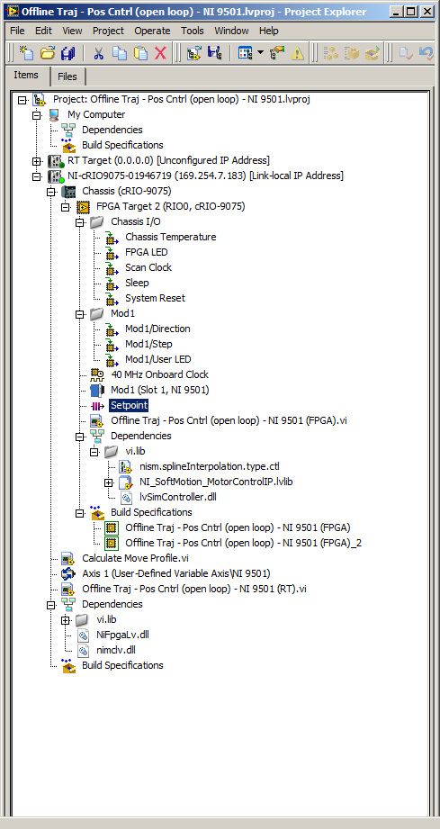
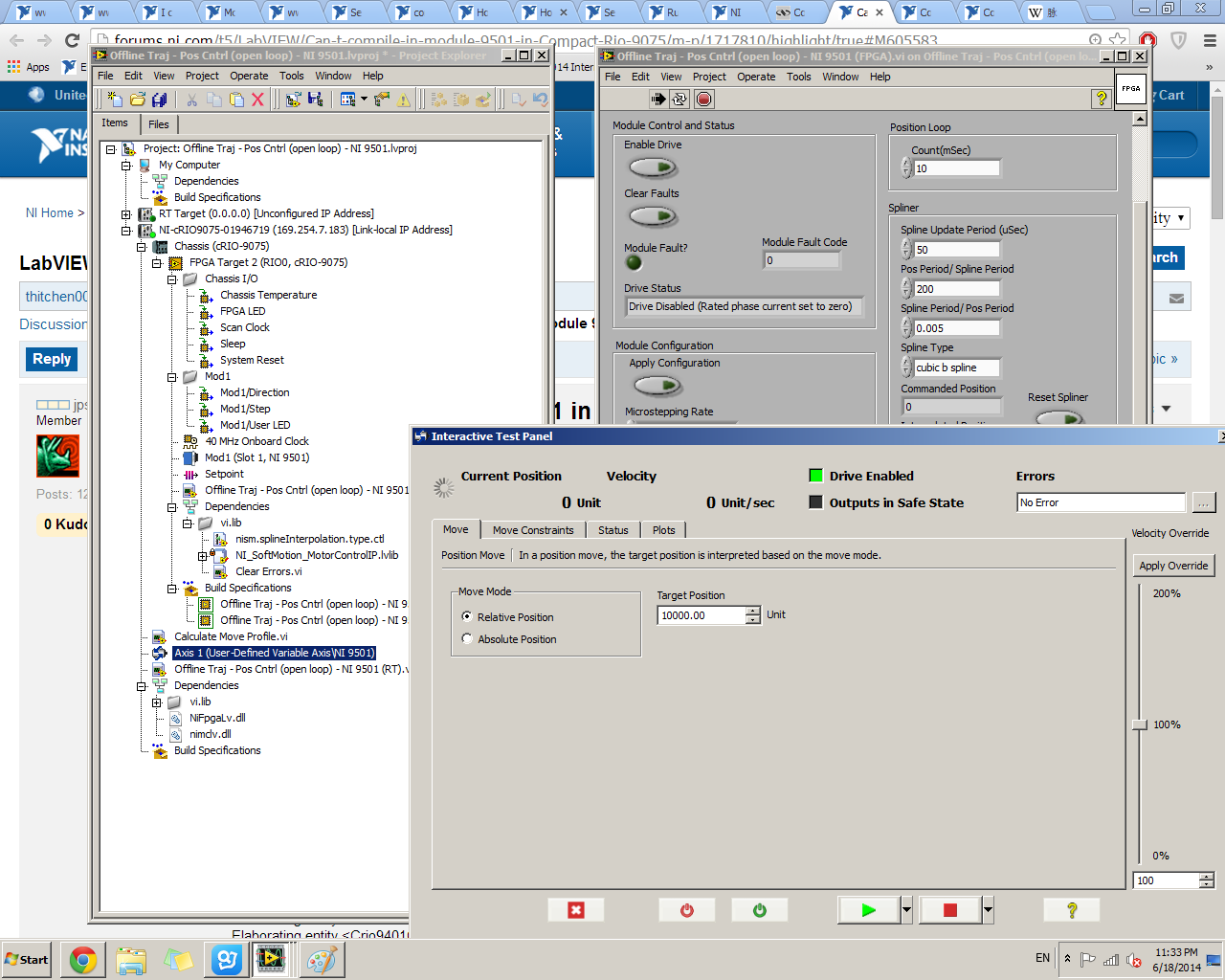
I work with cRIO 9075 with NI 9501 module to control a stepper motor. (Win7 Pro LabVIEW 2013 Pro)
I'm testing with the example "Offline Traj - Cntrl (open loop) NI 9501 Pos".
The FPGA is compiled by without error. But when I run the Interactive Test Panel for single axis, NI 9501 can never be activated, the LED indicator flashes. (indicating the drive is disabled) I enclose the photos of the tree of vi and panel test for your information. Please tell me what I did wrong. Thanks in advance.
-chen
PS Runing the vi "Offline Traj - Pos Cntrl (open loop) NI 9501 (RT) .vi" also looped stucks at a time where you have to activate the player.
Hi chen,.
If you want to use an axis with the interactive Test Panel, you will need to use another example of navigation NI 9501. I would start by the example of .lvproj Stepper drive (to start). After compilation, you should be able to use the interactive Test Panel to activate and move the engine. These examples may not compile on a 9075 because of the small FPGA.
To activate and move the engine using the Traj sample offline, you should have just compile the FPGA VI and then to run the Offline Traj - Pos Cntrl (open loop) - .vi NI 9501 (RT). If that do not allow the reader, make sure control of nominal current Phase is set correctly (it may not be null) and make sure that there are no errors.
Thank you
-
Unable to connect to EA6400 - Pings OK factory reset
I received the EA6400 from a non-techie friend who simply said this worked once and no longer works.
I got the camera and factory using the 30-30-30 reset. The device appears to come. Large. It is not connected to anything except the power.
I'm a bit oldschool so I plug my cable ethernet to p1 and launch my browser.
- Unable to connect 192.168.1.1.
- I open cmd and try to ipconfig/all default gateway is 192.168.1.1 and I have an ip address assigned to the scheme. I ping to the gateway and I get a response.
- I'm confused and look in the manual and online. I try www.linksyssmartwifi.com; unable to connect.
- I'm looking for the wifi network as described on the bottom of the router; except this wifi network is not created. I have try it with 3 devices, including a smarphone, none can see this wifi network.
The green light on the front of the router repeats this model:
- Fixed green
- Slow flashing Delierbate
- Fixed green
- Slow flashing Delierbate
I left it overnight, the same trend in the morning.
I'm at the end of my rope of troubleshooting. What are my next steps?
Thank you
try resetting it again by simply pressing the button reset (not the one blue) until the beginning of lites blinking then turn off the power for a few seconds then reapply. Make sure that the power supply is the right one for this router. the voltage must match exactly, but the nominal current of the power supply can be more than what is on the sticker on the router. then try to reconnect with an ethernet. the password should at this time there began to 'admin' (without the quotes)
Maybe you are looking for
-
I use a message filter to perform two actions on messages:(1) message copy of an imap folder(2) move the message to a local folder. Usually this works; the message is in the imap folder and local folder and is not in the Inbox. But about 10% of the t
-
Hello! I have some problems to upgrade my ios6 to ios9.2.1. Every time, when I try to do, there is a message "Unable to install Update" and if I choose the settings, next message button is "almost complete storage", but I have 8.2 GB available on my
-
Satellite A-L70-12W - HDMI only audio in stereo and 5.1 not send
Hello I have a question about my laptop's HDMI output. When I connect an HDMI cable to my tv and cable toslink from my TV to my receiver, my laptop still sends 2.0 sound to my TV. The TV I use is the LG 42LV3400-ZA, and he is certified Dolby Digital.
-
How to open windows xp without reboot pc__
How to open windows xp without disconnection Windows Vista
-
original title: BBC iplayer I can't listen to the radio online. I have fan any advice on the BBC website that is allowing cookies, download latest Adobe Flash and Java plug-ins but still no luck. I use a wireless connection and am currently in Italy.