type of digital output USB-6216
Hello
I am wanting to use the outputs digital on the USB-6216.
Are the open collector output? I couldn't find this information explicitly in the user manual. According to 6.4 Figure in the user manual, showing the connection LED to channel 1, it seems that the output must be open collector (to get off the power, turn on the LED). Is this correct?
Thank you.
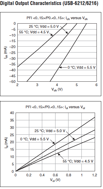
A push-pull output can drive an LED very well. Look at the specifications, page 8. It shows low and high current drive for outputs levels. This device has no collector lines opened.
Lynn
Tags: NI Hardware
Similar Questions
-
take the digital output USB-6001 always high or low in c
Hi all
I am new to the NI DAQ interface. I have a USB-6001 and I am trying to use this device to control some flowchart in C. What I want to do is:
* set digital output lines with high and low intensity and change their status as needed (in C).
I tested the device NEITHER Max--> Test panels and found that the device is capable to do that. Then I try to do in C. I have checked hace examples and function I use is one called "DAQmxWriteDigitalU32". I have problem in the understanding of its input parameters. I tried something with my own knowledge, but it does not work as I expected. Here is a test I did:
data uInt32 = 1;
Int32 wrote;
TaskHandle taskHandle = 0;
DAQmxErrChk (DAQmxCreateTask("",&taskHandle));
DAQmxErrChk (DAQmxCreateDOChan (taskHandle, "Dev1/port0/line7", "", DAQmx_Val_ChanForAllLines));
DAQmxErrChk (DAQmxStartTask (taskHandle));
DAQmxErrChk (DAQmxWriteDigitalU32(taskHandle,1,1,10.0,DAQmx_Val_GroupByChannel,&data,&written,));taskHandle = 0;
DAQmxErrChk (DAQmxCreateTask("",&taskHandle));
DAQmxErrChk (DAQmxCreateDOChan (taskHandle, "Dev1/port0/$line0", "", DAQmx_Val_ChanForAllLines));
DAQmxErrChk (DAQmxStartTask (taskHandle));
DAQmxErrChk (DAQmxWriteDigitalU32(taskHandle,1,1,10.0,DAQmx_Val_GroupByChannel,&data,&written,));I just want to set ' Dev1/port0/line7' and ' Dev1/port0/$line0"at a high level, but only ' Dev1/port0/$line0' answer me. The second parameter of the DAQmxWriteDigitalU32 function is numSampsPerChan. If I replace (currently 1) with a higher value, such as 100, I see that "Dev1/port0/line7" sends a number of 1 output, then back to 0. So I guess that the problem is just that I understand not all parameters for the DAQmxWriteDigitalU32 function. Is someone can you please tell me how I can set up a line of digital output 1 or 0?
Thank you!
Hongkun
Hello
I finally find a way to do it! The feature works very well, and my problem was not set the data value to write correctly. It seems that if I want to write a 1 to the port0/line1, I put "data = 2 ^ 1" rather than "data = 1", because by default it is the second bit of the port.» Similarly, "data = 2 ^ 7 ' high level to port0/line7. I find that this setting is surprising when you want to control an individual line. It seems more reasonable when you control the whole port. In any case, is to solve the problem!
Thanks anyway!
Hongkun
-
Type of output USB 6501 digital IO
Hi, I'm new to this software.
I use an e/s digital NI USB-6501 24 lines.
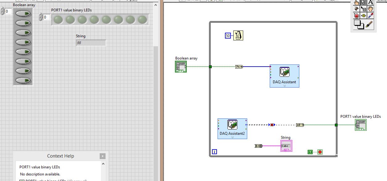
I physically wired PIN0.7:0 to PIN1.7:0, then all PORT0 go to PORT1
Click these buttons to table of Boolean, to set the output levels of PORT0, then having the signal wires to PORT1, which is then set accordingly, and then I want to ouput PORT1 using DAQ Assistant2 in:
(1) an array of Boolean LED
(2) a string indicating the value of the port in hexadecimal.
THE PROBLEM:
The DAQ Assistant2 outgoing data type is "table 1 d to unsigned long. The entry of the table that should receive it is "1-d array of boolean.
So, there is a data type mismatch.
How can I make this work? As you can see, I tried to place converters, I tried several converters, but I don't know what to do. Advice?
Stupid DAQ Assistant. I have no idea what is thinking want to a table. Personally, I just use the real DAQmx API. At least then you can say what is happening and it has less overhead.
A couple of other things:
You must move your controls and indicators for the acquisition of data inside the loop values. In this way they can be updated at each iteration of the loop.
Really, you must add a stop button. You need a way to cleanly stop your VI and do not use the button abandon in the toolbar.

-
Example of Calendar Type USB 6216
I use a USB-6216; I want to synchronize an output stream digital clocked by material with an analog output clocked by the material stream. I understand that there is no clock of digital I/O on the USB-6216, but this page (very helpful!) suggests that on a device of the M series, I can use one of the analog clocks - for example ' ao/SampleClock"- at the digital clock of data :
http://digital.NI.com/public.nsf/allkb/51754212AD10BDCE862573BD007BFDD2
However, when I try to configure a digital clock and task of "ao/SampleClock" (or "Dev4/ao/SampleClock", or "/ Dev4/ao/SampleClock") using DAQmxCfgSampClkTiming, I get an error saying that I can't use a sample clock for the tasks of the digital output on this device:
DAQmx error: the requested value is not supported for this property value. The value of the property may be invalid because it is in conflict with another property.
Property: DAQmx_SampTimingType
Required value: DAQmx_Val_SampClk
You can select: DAQmx_Val_OnDemandI'm trying specifically to synchronize the digital and analog output, but the links above for a very similar example, do the same for the entry:
http://zone.NI.com/DevZone/CDA/EPD/p/ID/4488
This example uses the same approach:
DAQmxErrChk (DAQmxCfgSampClkTiming (taskHandleDig, "/ Dev4/AI/SampleClock", note, DAQmx_Val_Rising, DAQmx_Val_FiniteSamps, sampsPerChanToAcquire));
When I run the present with my USB-6216 (code not changed other than to change the device name), I get exactly the same error.
The page above that talks about the use of this approach for devices of the series M apply not to the USB-6216? If so, what conditions should I I search in the specifications to understand if this is taken in charge or not?
Thank you!
-Dan
As far as timing goes, digital I/o on the multifunction data acquisition devices of NOR fall into three categories:
I. clocked by the software only
- MFDS "Legacy" (series E, series B)
- USB M Series (621 x) bus-powered.
- 6008/6009
II. NI hardware without internal synchronization engine (you will see this referred to as "correlation" in some places on the Web site of OR).
- Series M (622 x, x 625 x 628)
- CDAQ "Legacy" (9172)
III. clocked by a synchronization engine equipped material internal.
- X series
- current-gen cDAQ
I have no explanation for the inconsistent terminology through various OR marketing pages, "NI by material" and "clocked" are synonymous in my book.
It would have been nice to have more than one distinction of product name between 621 and 622 x x / x 625 / 628 x material of the M series. I imagine that much of the documentation has been written referring to devices'M Series' General before the x 621 has emerged and is now misleading and needs an update (they released for years even if it's not exactly an excuse...).
Best regards
-
NI USB-6501 digital output problem
Hello
I use DASYLab v.11 and I'm working on an interface with the NI USB-6501 where I'm putting a digital high on four ports.
With the module "NOR-DAQmx - digital input", I managed to read the digital inputs of the ' NI USB-6501 ".»
It's only the "NOR-DAQmx - digital output" I can't go to work.
Using 'NI MAX' of NOR I have easily can emmit my four LEDs in the way of my High/Low ports.
But not with DASYLab. When you use DASYLab tension on the ports remains unchanged.
Now, I have a switch module, generating 5/0, directly connected to the digital output module, which is assigned to my four output ports for my task.
I also tried with a module of relay between the two without success. I also tried to use 1.5 above instead of 5 without success.
I use the option 'Bus (0/5 supply) for the module "Digital output".
"NI Max", I configured the ports as "active drive.
Any suggestion of what I might be missing?
Thank you
Martin
Hmm, four ports, or four lines?
A port consists of eight lines. Each line can control an LED (ON / OFF ~ 0/5V).
If you have created a task to dig-out to control a port, 5V to this port sending sets all lines of this port to 'high '.
You need to 255 for each line one too high port (at the bit level: 128 + 64 + 32 + 16 + 8 + 4 + 2 + 1).<- eight="">
Or, you can create a dig out tasks to control four lines of a specific port.
Four lanes of the EEG DAQmx DigOut module.
Each of the channels of the modul will feed a single line of the task/device.
Four switches will then turn the lights, or turn off.
Make sure, that the 'bitposition' is the number of correct line (see picture).
-
Hello
I use the digital output to USB-6343.
Sometimes when I stop writing (clear the task) the rest at high output pin (I see it in the oscilloscope).
Is it possible to set that after earasing task output pin will always be low?
Thank you
Leonid
Thank you
-
USB 6008 digital output signal
I am VERY new to LabView and have been racking my brain trying to get digital output of my USB-6008. All I want is to be able to get a signal of + 5 V of my digital output when I click on a button. This signal opens a valve on a system I see so when it is pressed, it must stay open until I press the new button. It seems simple enough to me, but I'm not too familiar with LabView. Help, please!
Stripling07
You must first take the LabVIEW tutorials and then look at the links to get started with DAQmx .
The simplest program would be with the DAQ Assistant. Drop it on your schema, and then select digital output > digital line. Select the line when the wizard has completed, click OK. Wire a Boolean value in a table to build and the output of which is connected to the data entry. That's all. You can test the output of MAX (Measurement & Automation Explorer) with the test Panel. Do NOT test with your connected tap. Your valve may require more current that can provide the 6008.

-
Implementation of multiple digital outputs with a box USB-6009
Hi all
I write the code to implement a USB-6009 multiple digital channels, digital outputs independent. I have configured the function of "DAQmx create Channel" to create 'a channel for each line', but I can't understand how to access and control these channels separately. Pointers would be greatly appreciated.
Thank you!
I thought about it. Never mind.
-
Configuration of the digital output in the USB-6009
I have a card for the acquisition of data USB 6009. It seems that him when DAQ card is turned on, it is always default to digital output of 'High' or 'floating '. I want to default to 'low '. Is there some setting I want to 'program' the hardware DAQ to have all the outputs low when it is powered on the value? Right now I have manually enter MAX and adjust the level 'low '. Thank you very much for your help.
Sid05,
Yes, it's low of 820 ohms. Unfortunately, the way in which the system is built, it is the only choice you have without having to build external circuits such as SnowMule suggested.
AK2DM,
Thanks for pointing the USB-6000. Finally a real, if limited, the DAQ hardware. Nevermind, he was only 4 DIO lines.
Lynn
-
How to measure the digital output of the linear actuator on USB-6009?
Hello
I am a new user of Labview and need help to measure a digital input signal.
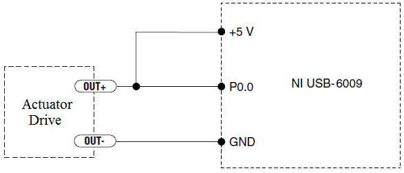
I have an actuator Bimba Original line electric with a motor continuous integrated with encoder, drive and the controller. The drive has a programmable digital output that I put as a tachometer output that emits pulses of square wave 100 per turn of the engine. I put the engine to make a total of 56 rev in 22 dry. I want to measure the speed of motor rotation labview real-time and synchronize it with a few other analog input signals. I wired the actuator for the USB-6009 case as shown below.
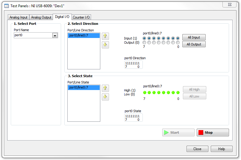
I opened the test i/o digital USB-6009 Panel and fix all the lines of port 0 as inputs. However, when I click on start and run the actuator, p0.0 led flashes, as indicated below.
Shouldn't the led blink in response to revolutions of engines?
I want basically to collect the drive pulse signals and convert them in rpm on labview.
ahsan2 wrote:
I have it wired correctly?
It would help if you do not attach the HIGH signal. Remove the + 5V in the circuit.
-
USB-6211 - digital output not supported?
Hi all
I can't use the USB6211 device port... I use daqmx with Delphi7 API functions.
First of all, I tried this:
DAQmxCreateTask('', @TaskDO);
DAQmxCreateDOChan (TaskDO, PChar('Dev1/port0'), ", DAQmx_Val_ChanForAllLines);
DAQmxWriteDigitalU8 (TaskDO, 1, 1, 1, DAQmx_Val_GroupByChannel, $FF, @written, nil);I had an error in the DAQmxWriteDigitalU8:-200012 (= digital output not supported). (???)
OK, I tried to disable autostart option based on DAQmxWriteDigitalU8 and insert a 'manual' start in the code:
DAQmxCreateTask('', @TaskDO);
DAQmxCreateDOChan (TaskDO, PChar('Dev1/port0'), ", DAQmx_Val_ChanForAllLines);
DAQmxStartTask (TaskDO);
DAQmxWriteDigitalU8 (TaskDO, 1, 0, 1, DAQmx_Val_GroupByChannel, $FF, @written, nil);
DAQmxStopTask (TaskDO);Now, I got the same error in DAQmxStartTask:-200012 (Digital Output not supported, once again). (?????)
I don't understand.. 'Digital output not supported "? USB-6211 has 4 lines! What is the problem?
I want to just turn on and off the lines from code...
-Cs George-
Well, finally I figured out...

Here is the solution:
DAQmxCreateTask('', @TaskDO);
DAQmxCreateDOChan (TaskDO, PChar('Dev1/port1'), ", DAQmx_Val_ChanForAllLines);
DAQmxWriteDigitalU8 (TaskDO, 1, @dummy, 1, DAQmx_Val_GroupByChannel, @bitmask, @written, nil);Digital output lines are on port1! Corrected parameter.
And the part of the interface of DAQmxWriteDigitalU8 had to be changed (in nidaqmx.pas).
I don't know why, but the AutoStart (dummy) parameter in the DAQmxWriteDigitalU8 function is ignored: function always starts task automatically, regardless of the value of autostart. But this isn't a problem for me.-Cs George-
-
NI USB-6009 digital outputs are active when connected to a PC - I'm not that
I have a small problem:
All outputs digital NI USB-6009 module become active when the module is connected to a PC when no VI is running.
As soon as I start my VI, which controls the module, all the outputs are disabled (now inactive).
How can I achieve this, outputs are inactive if the module is connected to a PC with no program running?
johanneshoer wrote:
I have a small problem:
All outputs digital NI USB-6009 module become active when the module is connected to a PC when no VI is running.
As soon as I start my VI, which controls the module, all the outputs are disabled (now inactive).
How can I achieve this, outputs are inactive if the module is connected to a PC with no program running?
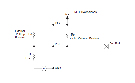
The USB-6008/6009 case has a pull-up internal (4.7 kOhm) resistance. This causes the outputs digital on the device to have a startup logic high State. t is not recommended to use some sort of resistance of menu drop-down. However, what you can do is add octal buffer like the 74HC541 stamp and a digital output to control the sorting of the 74hc541 state mode. Connect the OAS and CEO input signal. A Summit on the pins of the latter will be sorting the output of the buffer State. Therefore, no output signal will be present until you pull the stems of low control. The USB-6008/6009 case have a 5 volt output (200mA max), you can use the buffer.
-
Pull-up external USB-6009. digital output (open collector) allows onboard external + 2.5 V output?
Pull-up external USB-6009. digital output (open collector) allows onboard external + 2.5 V output?
Hello
I want to config output digital USB-6009 to + 2.5 V above and 0 V digital output low. I know I can config USB-6009 digital output open collector with resistance to pull-up external, that can be applied with + 2.5 V power source.
My question is: can I use USB-6009 Board + 2.5 V output as the current source of resistance to pull-up? What resistance is a good number for the resistance to pull-up, if I can use this configuration?
Thank you much for the help.
Cathy
Hi Cathy,.
The digital USB 6008 front-end server looks like this:
So, there is actually an internal pullup to 5V 4.7 kOhm resistance when the device is configured to open collector.
If you want to display 0 to 2.5 V, I would look in a resistance of polarization of 4.7 kOhm between c and ground (according to the rest of your tour).
Best regards
-
USB-6008 to give the digital output
Hi all
I was wondering anyone at - it base an example of an exercise using USB 6008 to give a digital output of a VI in Labview.
I am very new to the use of the USB 6008 AND Assistant DAQ and so far I've had reading a temperature, next step is I want the USB-6008 to give a + 5v output when the temperature reaches a certain value, I built a Labview 2009 VI for the temperature reading, but now I'm stuck on this piece.
Any help is appreciated! or if there are examples of laboratory exercises that exist that I can perhaps draw.
Hi Marko
Please take a look at the link that has some interesting and intuitive video to use the USB-6008 housing and how to set up the device for several applications in LabVIEW below. Please take a look at the step by step videos and let me know how you go. They are under the tab '"virtual Demos.
-
Digital output of 6289 USB to the function generator
Hi ppl.

I have a DAQ USB-6289 card I use M series to interface with a programmable frequency AD 5932 generator (hope it's not breaking all the rules
 )
)In the datasheet of the http://www.analog.com/en/rfif-components/direct-digital-synthesis-dds/ad5932/products/product.html AD5932
It is the interface series (FSYNC, SCLK, SURLABASEDESDONNEESDUFABRICANTDUBALLAST).
I'm using LabVIEW to generate a digital output and help the Council 6289 to send the signal to the ad5932.
The problem is the following:
(1) I am an engineer in chemistry and new LabVIEW and electronics
(2) I don't understand how the digital signal and the FSYNC SCLK and SURLABASEDESDONNEESDUFABRICANTDUBALLAST are related... Sorry for the very basic question...

Hope that's not too much to ask, but if someone could suggest a tutorial or examples it would be EXTREMELLY appreciated...
Thanks for any input because I'm really stuck on this point.
See you soon
You need to find is the complete technical data on the A/D. Who will explain what each of these pins and the time served. It looks like an SPI interface. OR sell the 8451 for this programming. You can or perhaps are not able to use the 6289. I recommend a search of "SPI" to see if anyone has created a VI.
Maybe you are looking for
-
Disable the infrared receiver on Satellite A100 (PSAA9A)
After the discovery of a new TV remote uses the same frequencies as my computer, my laptop now turn on or turn off whenever I have change the channel on the TV. I would switch the infrared receiver on my computer to avoid this problem. I assumed it w
-
Thread freeze trying to navigate the menu
I'm currently developing a monitoring software for an industrial machine. On the main thread, I treat all the events of the user interface, and in an AsyncTimer, I am purchasing data (via CPB). I protect my data using CmtNewLock, CmtGetLock and CmtRe
-
Windows Update - updates is not complete.
I've updated Windows updates automatically every day, and it has always worked well. However, since February 13, 2010, it seems stuck in a loop. No error, it just shows continuously "Searching for Updates" for hours! If I stop the laptop that I ge
-
Como configurar esta application microsof visual c ++ 2010 Express program path: am files/microsoft Visual Studio 10.0 / commom7/IDE/vcexpres.exe
-
Miss me the path to address starting by ' AppData\Roaming\Microsoft office\...When I do a search on the normal template, the address is displayed but when I followed the path, it is not there.I can just type in the records for the way I want?