USB-6009 HAVE and AO
Hello
I have a USB - 6009 DAQmx. I want to measure an analog input with the highest possible sample rate (48 kHz). At the same time, I need an analog output in voltage from 0 to 5 Volts, lets say 2 minutes of the ramp. Both of these tasks require no synchronization of relatives. With respect to the specification, the highest rate of the AO is 150 Hz. It's ok for my application.
So far I use the internal clock of the device, and the OD does not work with a timing of software. Is it possible of ramping regardless the voltage output and at the same time reading analog input? If not, is there a work around for this device?
Thanks for the tips!
Kind regards
HI Blook,
your VI test seems ok. Of course, given that the AO is in sync SW and you run it on a Windows platform may be you will see some jitter on the output. But you said, you don t need a thight synchronization, so it shouldn´t be question.
For what concerns the way in which LV manages data acquired from a multiplexed DAQ card, that should be kept in mind
that the timestamp of the waveform is generated from the driver on the PC and not directly on the map. This means that even if the sample of both channels are acquired in two different
moments (like you supposed to separate by the time of the ADC) this will be transparent to the SW and they will be considered granted exactly at the same time.
National Isntrumetns offers also simultaneous of sampled acquisition card (and not multiplexed) to overcome this problem.
Best regards
André
Tags: NI Software
Similar Questions
-
Using the DAQ USB-6009 meter and an analog input voltage at the same time.
Hello
Currently, I'm reading the two channels of voltage with the USB-6009. It happens that one of the channels is the output of a digital coder, and it would be much easier to use it directly to the PFIO entry that is defined as a counter. The problem I am facing right now, it's that I can't use the DAQ Assistant to use the analog voltage to a channel and the digital channel counter at the same time. Once I put the DAQ Assistant to read the input from analogue voltage, I won't be able to add analog inputs. And as I put the DAQ Assistant to use the PFIO as a counter, I can add more entries to read analog voltage is.
I wonder if it is possible to solve this problem using the lower level data blocks? Another solution would be to read two channels in analog input voltage and that the use of Matlab to process data resulting from it, since I was not able to do the counting to work simultaneously with the acquisition in Labview to impulses.
Hope you guys can help out me.
Thanks in advance.
Using a simple wizard of DAQ is incorrect. You need one to acquire analog inputs and one for the meter.
-
Hello
I use several USB 6009 units and with some of them seems to have some lag in differential mode, I with 0 to 1V range. Grounded the two terminals with resistors as shown in the tutorial OR «wiring field and noise review...» "seems to fix the problem for some of them, but for those that I have not the slightest compensation first, the ground gives me offset. Can someone please suggest?
Thank you
DS
DS,
Please submit your question in the Forums of NOR. Are you trying to take a differential measurement? What features are you try to measure it and what channels the drop-resistance work with and what channels do they not work with?
-
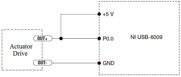
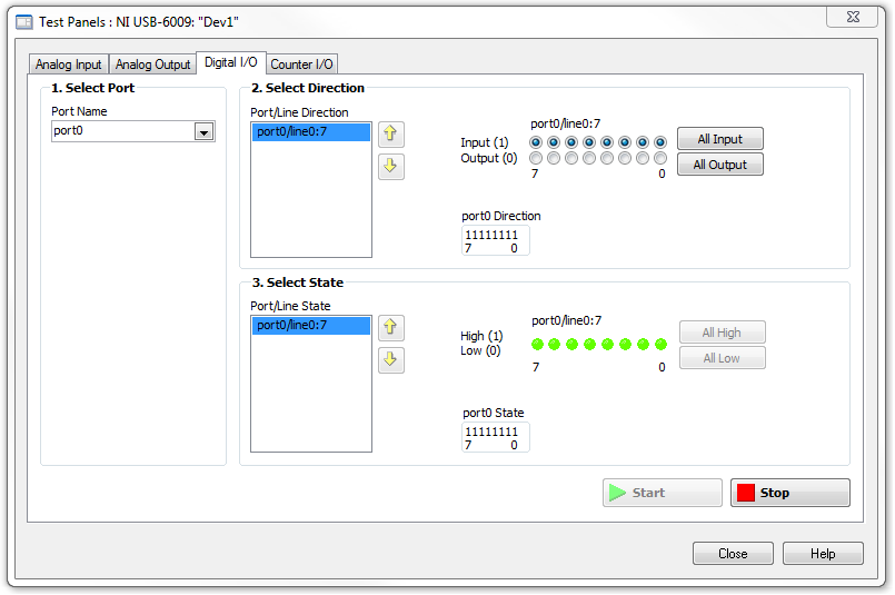
How to measure the digital output of the linear actuator on USB-6009?
Hello
I am a new user of Labview and need help to measure a digital input signal.
I have an actuator Bimba Original line electric with a motor continuous integrated with encoder, drive and the controller. The drive has a programmable digital output that I put as a tachometer output that emits pulses of square wave 100 per turn of the engine. I put the engine to make a total of 56 rev in 22 dry. I want to measure the speed of motor rotation labview real-time and synchronize it with a few other analog input signals. I wired the actuator for the USB-6009 case as shown below.
I opened the test i/o digital USB-6009 Panel and fix all the lines of port 0 as inputs. However, when I click on start and run the actuator, p0.0 led flashes, as indicated below.
Shouldn't the led blink in response to revolutions of engines?
I want basically to collect the drive pulse signals and convert them in rpm on labview.
ahsan2 wrote:
I have it wired correctly?
It would help if you do not attach the HIGH signal. Remove the + 5V in the circuit.
-
How to configure the PFI0 terminal on the USB-6009 case as came event counter
I'm watching the 8 inputs on the USB-6009 case and when fires Terminal PFI0 start saving the data.
Y at - it and why to read the 8 inputs while monitoring the PFI0 terminal? I appreciate any help!
Hi yacs1,
You can certainly do. I assume that you already have your 8 entries read correctly. Everything you have to do is now to put a statement button in your loop that is controlled by your pfi0 line. If this line is high, then save the data, if it's low, then only display data of your control. If you need help reading the pfi line, open finder example under help > find examples. Then go to the material input and output, reading Dig channel DAQmx, numerical measures. If you need help logging data, go in Fundamentals, file input and output, and then depending on what type of file you want to write to, find the appropriate example (IE write into text file).
Let us know if you need more assistance,
Ryan
Technical sales engineer
-
Parallel peripheral USB - 6009 DAQmx
Hello, im using an NI USB-6009. And I have to read two analog inputs, to write two outputs analog and two digital outputs. All this at the same time.
It works if I connect them successively, but then the VI is too slow for a good measure.
So my question is, can it work generally if the data flow is not hollow hollow hole in the chain, but rather by coincidence given the individual parts of the VI?Now, it does not work.
First comment would take the task of starting/clear daqmx out of the while loop. Start tasks before entering the loop. then as soon as you exit the loop (when you press the stop button) clear tasks. There is no need to start and clear each loop
-
OR USB-6009 and Tek TDS2024C comparesment
My apologies if this topic was already discussed, but I searched through the forum and manuals and can't find anything.
I have a problem with measurements in parallel with TDS2024C NI USB-6009 and Tek.
I measured the noise high frequency on 10 s window.
I used the data logger with a frequency of 40 kHz connection in parallel with TDS2024C (which reached 250 Hz on 10s window) and got very different results.
On the attachment figure, first signal comes from screenshot of scope data and the second of the NI USB-6009 islogged.
Can someone explain to me why are these so different results?
Different sampling frequencies could easily explain it. Try to run the USB-6009 case at the same rate as the scope and see what you get. I also think that the TDS2024C has fewer bits in the ADC, which could also cause differences.
-
Device driver in Linux and ready to compile application user for USB-6009
Hello
I intend to use the acquisition card to USB-6009 data under Linux platform. To do this, I need driver linux for acquisition card data USB-6009 and some read-compilation-and-program to use "user application" which can take samples of the card, to implement some buffering or write to the file. It would be beneficial if I could also get sample code to generate a sinusoidal low frequency signal, using the D-to-A converter available on the Board of Directors.
Also I need installation instructions for the NOR-DAQ software under standard linux environment.
Thank you for your quick and detailed response,
Adeel Malik,
Research engineer,
Institute of telecommunications research,
Mawson Lakes Boulevard,
Mawson Lakes,
South Australia, 5095,.
Australia
Mobile: + 61 0404 030 071
E-mail: [email protected]
Hello Adeel,
You will need to install the libstdc ++. so.5 Library. A Google search has a few useful discussions that give more information on the procedure to follow if you are not sure:
Let me know if you have installation problems - you can also try to contact redhat support if you are having problems. If you have problems, please post so we can document the troubleshooting procedure to help all customers who may experience this problem in the future. Thanks for posting!
-John
-
How to synchronize clocks on USB-6009 and USB-6343
Hello
Can anyone provide an example on how to synchronize clocks on USB-6009 and USB 6343?
I checked the example screws, but it shows that we must use 2 counters, one as the clock of the source and the other as a trigger. But only 1 CLK 6009.
I read the user manual and it is mentioned to use (AI/start-trigger) in order to use PFI0 as source.i am somehow confused about how to achieve this.
Furthermore, what would be the physical connections?
Thank you
LV_Enthu
Unfortunately, you won't be able to completely synchronize your devices USB-6009 and USB-6343. As you have seen, the 6009 has only a meter on board.
You can certainly use PFI0 as an input to start your tasks at the same time digital release. However, the 6009 is a strictly timed by the software. There is no way to import an external sample clock.
-
How to open and close an electronic shutter with LabView 8.5.1 using an NI USB-6009 case?
Also, I need to set up a timer so that the shutter is open for 15 minutes and closed for 30 minutes. It has to do 500 times.
The USB-6009 case is a relatively new device, and LabVIEW 8.5.1 is a fairly old software. You should check to be sure that you have the corresponding to your version of LabVIEW (DAQmx) drivers that support of this material. It sounds as if you put it in place to MAX and control the output manually, which is a good sign. I don't have access to the version 8.5.1 and I do not exactly remember which functions he supported, but the attached picture shows a simple diagram in a new version of LabVIEW that would do what you want. Of course, you should test with shorter and less iterations because it takes more than 2 weeks to complete! Add any controls, indicators and the error checking you want.
Rich
-
Hi all forum, this is my first post so I apologize if I posted in the wrong section.
I'll briefly explain my situation.
I have to connect the USB box - 6009 DAQ with an automaton: the application consist in an analog acquisition task, began of the automaton, awaiting a signal for the task. 24V PLC work, so I found a map of external interface based ULN2803 and relay for the adaptation of signals [http://www.datasheetcatalog.net/it/datasheets_pdf/U/L/N/2/ULN2803.shtml].
ICR accept an entry order 5V TTL, but in the datashet (and also on the figure), is specified that the activation voltage is approximately [email protected].
Now, my question is: what is the correct configuration of the digital port on data acquisition between open collector and push - pull? Also the maximum of open collector current is estimated to be 0.6mA, if I can damage the USB-6009 case in this configuration?
Another question, on the side of digital input. I think to use another active relay 24V, that switch between 0V and 5V digital input line. Y at - there no consideration to take? Should what configuration I use?
PS: the interface card would be shipped within a few days, so I don't have it at the moment.
Waiting for a response.
Best regards
Marco
Hello Marco,.
Although you don't need an external resistor to DO more.
With respect to the entry, as I told you yesterday that you don't need an extra resistance, you should be fine with your current configuration.
Ciao,.
Andrea
-
Sinusoidal linear encoders Heidenhain 11 (micro) App and USB-6009
Hello, I need to read the two linear encoder sinusoidal signals App 11 Heidenhain (micro), described on page 37: http://www.heidenhain.com/fileadmin/pdb/media/img/208_945-28.pdf
I have been using a standard oscilloscope and merged the two signals on a X - Y axes screen two, to display a circle to inspect if the glass scale is OK.
If the glass scale is OK, then the circle is relatively stable in size and position when you move the receiver along the scale.
Now, I would do the same test with a USB-6009. Is this possible? The two signals should be treated as current input analog? In this case is 11 specifications USB 6009 operator?
Thank you
Luke
-
Using the NI USB-6009 case to generate a 12VDC output and output current of 300mA
Hello
I use the OR-USB-6009 my power supply for a 12VDC with drive current of 300 solenoid my. Initially, I used a non reverse Op-amp circuit and Inverter circuit operational amplifier to get the + 12V and - 12V output but I could not get the current I required. Should I use a transistor?
Please find attached photos. Any input would be appreciated.
Thank you
Adam
Well, really depend on your piercing circuit. But I used most systems use the transistor to set the voltage of the device to 0V. So when your DIO is high, the output is actually 0V (low). So using a converter chip, your release of the DIO will be sort of the output circuit. If you get the right IC, then the inverter will give you also a few extra current to drive your transistor.
-
Digital and analog inputs simultaneously - NI USB-6009 and NI USB-6212 - ANSI C
Hello
I'm reading at all times and at the same time analog and digital inputs. Digital and analog samples must be sampled at the same clock and acquisition should be started (triggered?) at the same time (I don't want, after some time, analog reception more digital samples - the opposite is also true).
I found an example (in C source code) "National Instruments\NI-DAQ\Examples\DAQmx ANSI C\Synchronization\Multi-Function\ContAI-Read dig Chan" and tried to run with two USB cards: NI USB-6009 and NI USB-6212. Unfortunately, the two results by mistake, as described below:
DAQmx error: the requested value is not supported for this property value.
Property: DAQmx_SampTimingType
You asked: DAQmx_Val_SampClk
You can select: DAQmx_Val_OnDemandTask name: _unnamedTask<1>
State code:-200077
End of the program, press the Enter key to exit-Is it possible sync analog and digital acquisition in the paintings?
-If so, how?
Thank you
Hello tcbusatta,
Two of these modules, USB = 6008 and USB-6212, support only timed software inputs and digital outputs. This means that you cannot define material timing (like finished sampling or continuous) for these modules. Digital lines can be retrieved or written once to each call DAQmx read.
This means that you will not be able to get any type of synchronization tight between the analogue and digital channels. You will need a Board such as the NI USB-6341 in order to synchronize the AI and DI closely.
-
Can I synchronize and AI on USB-6009 with meter?
Hi all
I use USB-6009, LV 8.5 under windows XP. I want to generate signals synchronized with Amnesty International. I know that I can not use the sample as DO clock clock. But can I use the card counter to synchronize and AI? And can someone give some similar examples? Thank you!
Best wishes
Bo
The unit will display whenever you call writing DAQmx. It is more complicated than that. And synchronization is practically based on the flow of data and when you want to generate the digital output from the analog input.
Maybe you are looking for
-
New update of FireFox 29 guard affected by errors "Firefox is alreay underway of execution".
I am running Windows 8.1 and has been using Firefox in full transparency. Since the upgrade to Firefox 29, he guard affected by errors "Firefox is already running". Then I have to stop in the Task Manager to start. I deleted the parent.lock several t
-
Satellite M40 resume Hibernate when the lid is opened
My M40 RESUME from hibernation/sleep as soon as I open the cover, currently in the standby power button action is set to Hibernate and cover is set to do nothing do I put into hibernation and close the lid when I open windows back it doesn't wait for
-
How to deal with a Message of end of contract
The agreement has already expired, although the license expiration date in a few months. Should I take this serious message, since all the software works very well!
-
Is there a default value for NC_ATTRIB_BKD_PERIOD
I got a project and the value of NC_ATTRIB_BKD_PERIOD has been set to 10. I changed this value to 1 (I guess that's milliseconds) and the software runs much faster save about 20 seconds on a second test period formerly 60. I have used NEITHER CAN bef
-
Enable SNMP to send blocked due to the loop network interface
Dear community, We had a customer who has created a loop on his layer access and STP blocked some interfaces in order to protect the network. Normal behaviour until now, but we would like to receive the device, when these events occur, usually when a